Appendix B _______________________________________________________ RVP900 Packaging
VAISALA______________________________________________________________________ 353
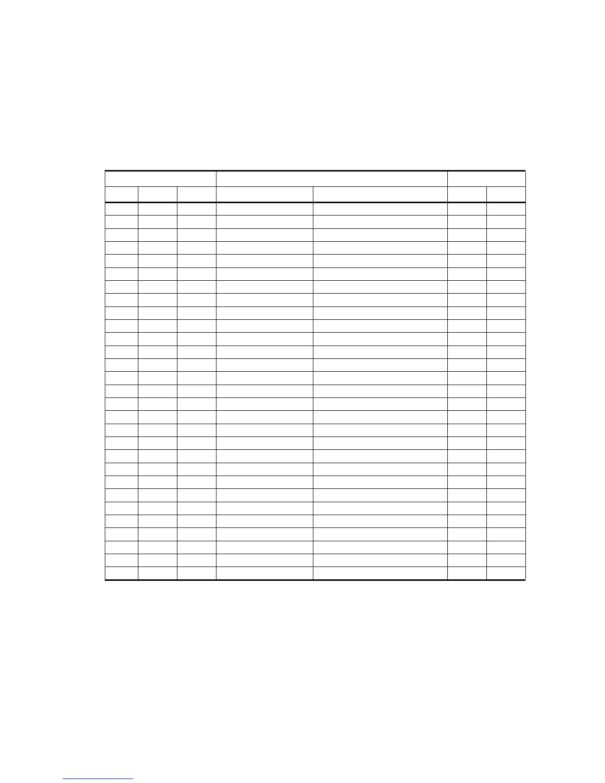
female “D” connector. The cable wiring and internal signal names are
shown in Table 17. The cable provides 10 RS-422 signals, 10 TTL signals,
three differential analog input A/D signals, and +5V and -5V auxiliary
power from the IFDR. Standard cable length is 1 meter.
B.5 Optional DAFC
The Digital Automatic Freq Control (DAFC) module is used on the
RVP900 for magnetron systems to interface to a digitally controlled
STALO. The DAFC is driven from the Trig-A trigger output SMA of the
IFDR module. DC power needs be provided by running discrete wires, but
Table 17 Generic Interconnect cable for IFRD Analog/Digital
I/O
D Connectors Index
51-Pin 25- Pin 37- Pin Signal Name Softplane Signal J3 J6
1/19 1/14 — GPDIFF_PIN_LP/N Comm.diff 0 10
2/20 2/15 — GPDIFF_PIN_LP/N Comm.diff 1 11
3/21 3/16 — GPDIFF_PIN_LP/N Comm.diff 2 12
4/22 4/17 — GPDIFF_PIN_LP/N Comm.diff 3 13
5/23 5/18 — GPDIFF_PIN_LP/N Comm.diff 4 14
6/24 6/19 — GPDIFF_PIN_LP/N Comm.diff 5 15
7/25 7/20 — GPDIFF_PIN_LP/N Comm.diff 6 16
8/26 8/21 — GPDIFF_PIN_LP/N Comm.diff 7 17
9/27 9/22 — GPDIFF_PIN_LP/N Comm.diff 8 18
10/28 10/23 — GPDIFF_PIN_LP/N Comm.diff 9 19
18 13 — GND
11/29 — 1/20 TTLIO_PIN/GND Comm.ttl/GND 0 10
12/30 — 2/21 TTLIO_PIN/GND Comm.ttl/GND 1 11
13/31 — 3/22 TTLIO_PIN/GND Comm.ttl/GND 2 12
14/32 — 4/23 TTLIO_PIN/GND Comm.ttl/GND 3 13
15/33 — 5/24 TTLIO_PIN/GND Comm.ttl/GND 4 14
16/34 — 6/25 TTLIO_PIN/GND Comm.ttl/GND 5 15
17/35 — 7/26 TTLIO_PIN/GND Comm.ttl/GND 6 16
36/37 — 8/27 TTLIO_PIN/GND Comm.ttl/GND 7 17
38/39 — 9/28 TTLIO_PIN/GND Comm.ttl/GND 8 18
40/41 — 10/29 TTLIO_PIN/GND Comm.ttl/GND 9 19
42/43 — 12/30 AMUX_POS_PIN AMUX P0/N0 0 3
AMUX_NEG_PIN
46/47 — 14/32 AMUX_POS_PIN AMUX P1/N1 1 4
AMUX_NEG_PIN
50/51 — 16/34 AMUX_POS_PIN AMUX P2/N2 2 5
AMUX_NEG_PIN
44/45 — 18/36 V_5P0_GPIO/GND +5V/GND
48/49 — 19/37 V_N5P0_GPIO/GND -5V/GND
 Loading...