USER’S MANUAL__________________________________________________________________
90 __________________________________________________________________ M211322EN-D
The "AB" position of the 3-pin "Alarm" jumper (H9) connects the Fault
Status signal to Pin #4 of the terminal block, whereas the "BC" position
grounds that terminal block pin. A second ground can be made available at
Pin #5 of the terminal block by installing a jumper in the "BC" position of
the "Spare" 3-pin jumper (H10). This second ground could be used as a
ground return, when the Fault Status line is driven off of the terminal
block. The "AB" position of the "Spare" jumper is reserved for some future
input or output line on the terminal block.
A crystal oscillator is used to supply the operating clock for the on-board
logic, and there are two choices of frequency to use. If jumper H2 is "Off",
the crystal frequency should be equal to the IFD sampling clock f
aq
, and if
H2 is "On", the frequency should be (0.75 × f
aq
).
Additional information about using AFC can be found in Section 4.2.6 Mb
— Burst Pulse and AFC on page 126 and Section 6.1.3 Automatic
Frequency Control (AFC) on page 187.
3.4.1 Example Hookup to a CTI MVSR-xxx
STALO
Here is a complete example of what would need to be done in hardware and
software to interface the DAFC to a Communication Techniques Inc.
digital STALO. The electrical interface for the STALO is through a 26-pin
ribbon cable, which carries both Control and Status, as well as DC power.
This cable can be crimped onto a mass-terminated 25-pin "D" connector
(with one wire removed) and plugged directly into the DAFC. The
resulting pinout is shown in Table 6 on page 88.
The STALO frequency is controlled by a 14-bit binary integer, whose LSB
has a weight of 100 KiloHertz. In addition, the "Inhb" pin must be low for
the STALO to function. Power is supplied on the +5 V and +24 V pins, and
two grounds are provided. An "alarm" output is also available.
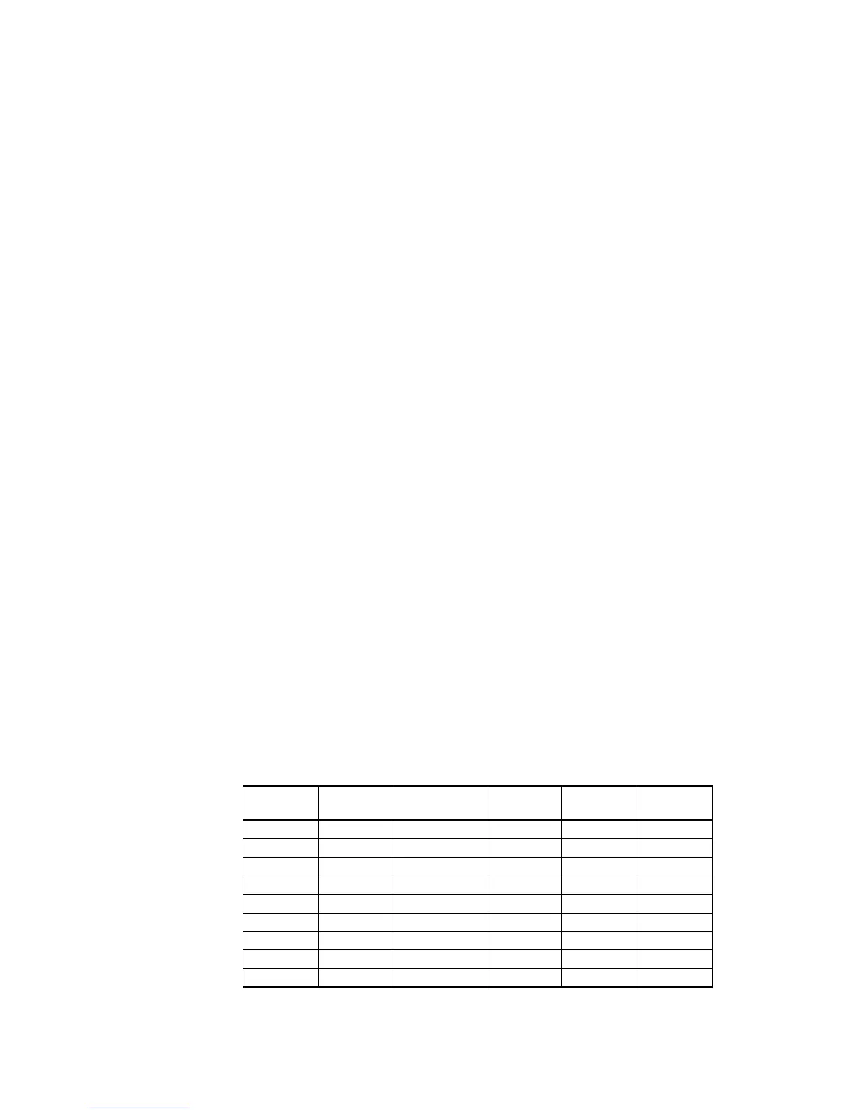
Table 6 Pinout for the CTI MVSR-xxx STALO
Ribbon
Pin
"D" Pin Function Ribbon
Pin
"D" Pin Function
1 1 Ground 2 14 --
32+5V 415--
5 3 +24V 6 16 --
7 4 Alarm 8 17 --
95-- 10 18 Bit-0
11 6 Bit-2 12 19 Bit-1
13 7 Bit-3 14 20 Bit-10
15 8 Bit-11 16 21 Bit-4
17 9 Bit-9 18 22 Bit-5
 Loading...