Chapter 3 _______________________________________________________ Hardware Installation
VAISALA_______________________________________________________________________ 89
wire to connect each bit to its corresponding pin. This is somewhat tedious,
but hopefully one of the three formats is a reasonable starting point for
doing the wiring. By far, the most preferable solution is to use the Pinmap
uplink protocol (available since Rev.19), which allows for complete
software mapping of all 25 external pins.
Ground, +5 V, and +24 V power supply pins on the "D" connector should
be connected with wirewrap wire to the nearby power and ground posts
H6, H7, and H8. The PLD jumpers for these power supply pins must not
be installed. Two 3 K/6 K resistive terminators are also available at H5 for
pulling pins up to approximately +3.3 V, when that is appropriate. Unused
"D" connector pins should remain both unwired and not jumpered.
The DAFC board runs off of a single +5 V power supply, which can be
applied either from the STALO through the "D" connector, or externally
through the terminal block. There are also provisions for supplying +24 V
(approximately) between the terminal block and the "D" connector, which
is handy for cabling power to a STALO that requires the second voltage.
Two green LEDs indicate the presence of +5 V and +24 V. Terminal block
Pin #1 is +5 V, Pin #2 is +24 V, and Pin#3 is Ground. Pin #1 is the one
nearest the corner of the board.
There is an option for having a "Fault Status" input on the "D" connector
of the DAFC. Since the board is completely passive in its connection to the
uplink, the fault status bit does not affect the uplink in any way. The bit is
simply received by the board (with optional polarity reversal) and driven
onto the terminal block (P3), from whence it can be wired to some other
device, for example, a BITE input line of an RCP02. A yellow LED
indicates the presence of any external fault conditions.
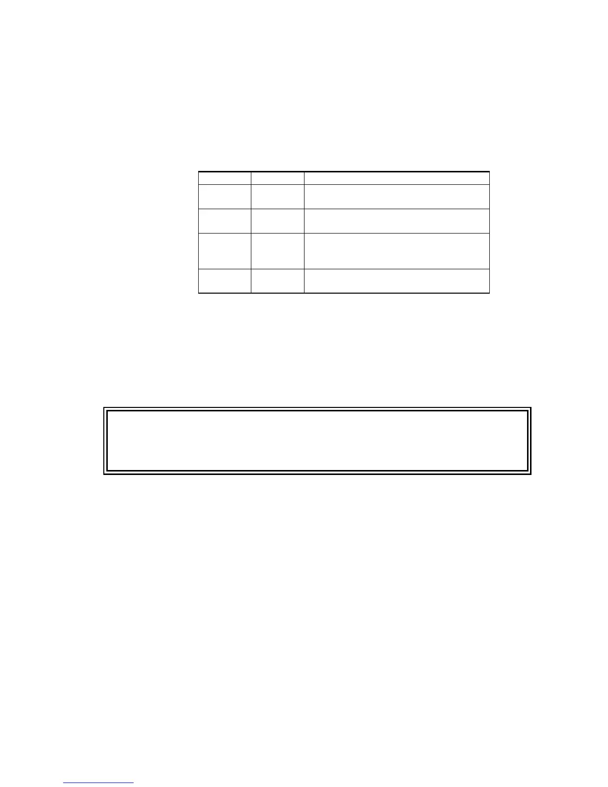
Table 5 DAFC Protocol Jumper Selections
H4 H3 Function
On On AFC-16 format, Bits<0:15> on Pins<1:16>,
Fault input on Pin 25
On Off AFC-16 format, Bits<0:15> on
Pins<25:10>, Fault input on Pin 3
Off On AFC-16 format, Bits<0:15> on Pins<18, 19,
6, 7, 21, 22, 23, 11, 10, 9, 20, 8, 12, 25, 13,
24>, Fault input on Pin 4
Off Off Pinmap format, software assignment of all
pins
WARNING
It is important that the jumpers only be installed for pins that carry TTL
inputs or outputs destined for the on-board PLD. The jumpers must be
removed for all power supply pins, and for unused and reserved pins of
the external device.
 Loading...