USER’S MANUAL__________________________________________________________________
244 _________________________________________________________________ M211322EN-D
and thus:
The angle Ø represents a velocity phase angle in [- π, π] , but with respect
to an enlarged unambiguous interval. Thus, by simply differencing the
folded angles from the high and low PRFs, we obtain an angle that is
unfolded to a larger velocity span. Similar reasoning shows that the 4:3
ratio gives a factor of three improvement over V
uh
, and 5:4 gives a factor
of four.
In practice, the unfolded angle Ø is not in itself a suitable velocity
estimator. The reason is that the variance of Ø is equal to the sum of the
variances of each of its components, that is, twice that of the individual
measurements alone. If the target is at all noisy, then this increase in
variance can be severe. Rather than use Ø directly, the RVP900 uses it only
as a rough estimate in determining how to unfold the individual velocity
measured from each PRF.
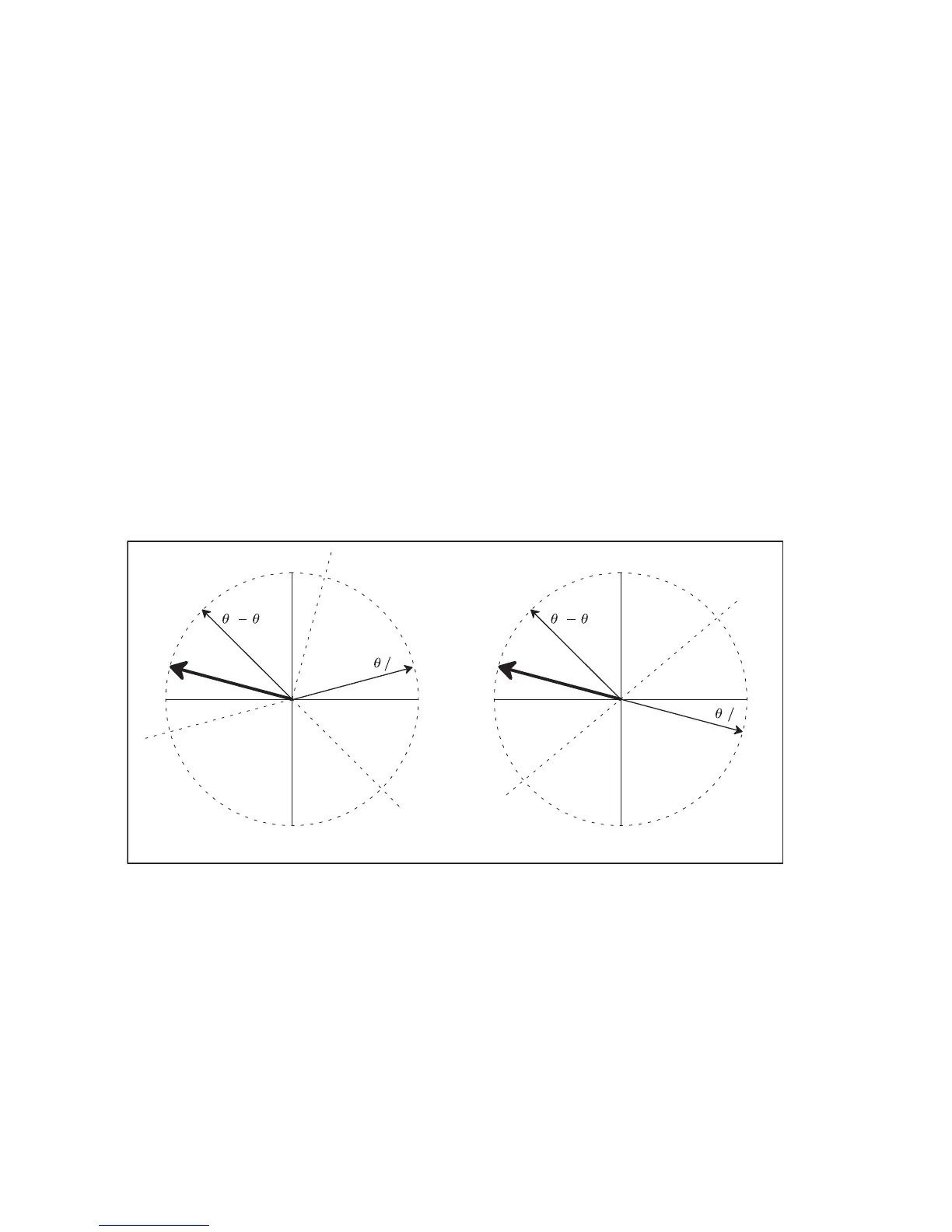
0916-063
Figure 51 Dual PRF Concepts
This technique is illustrated in Figure 51 on page 242. The figure shows
how the low-PRF and high-PRF angles are unfolded based on the
difference angle. The diagrams show phase planes representing the large
unfolded velocity interval, and the locations of various vectors on those
planes. Referring first to the right figure, the difference angle is plotted,
and the plane is divided into two equal size regions, one of which is
centered on the difference vector. The high-PRF angle is then divided by
two and plotted. The resultant unfolded velocity angle must either be this
 Loading...