USER’S MANUAL__________________________________________________________________
460 _________________________________________________________________ M211322EN-D
- TTL input signals should have a 5 V unidirectional TVS device
on them
- TTL output signals should have a 5 V unidirectional TVS device
on them
- BNC Analog Inputs:
- LOG_VIDEO signal (AMUX0) is a 0.5 to 2.5 analog signal with
very low frequency/DC characteristics
- Spare test input (AMUX1) is connected to resistive network and
capacitor to allow flexibility in maximum signal. As configured,
it will accept 3V input low frequency signal.
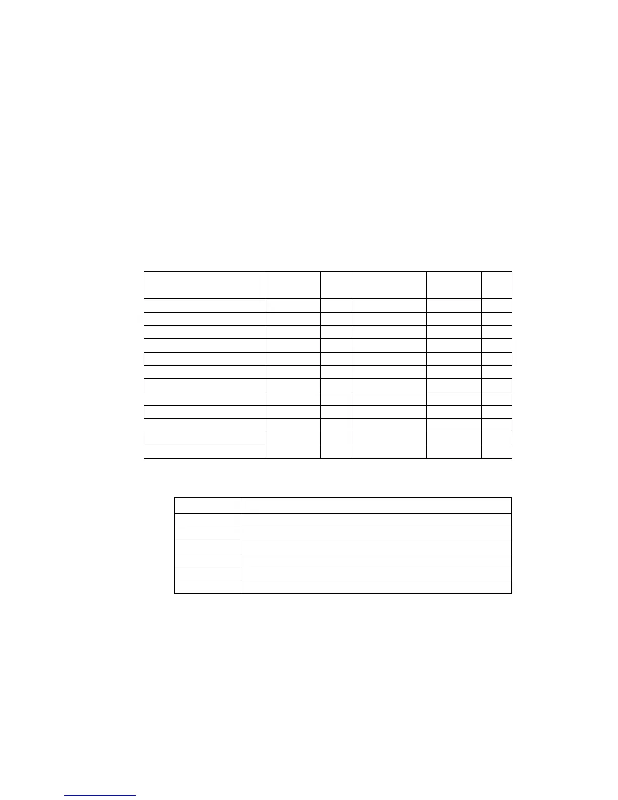
Table 28 RCP902 WSR98D Interface to Radar
Connector Size Designator TYPE Connector
Size
Designator TYPE
D-SUB STR 37 POSITION J3 PLUG BNC 50 OHM J20 JACK
D-SUB STR 9 POSITION J4 RCPT BNC 50 OHM J21 JACK
D-SUB STR 37 POSITION J7 RCPT BNC 50 OHM J22 JACK
D-SUB STR 9 POSITION J8 RCPT BNC 50 OHM J23 JACK
D-SUB STR 15 POSITION J9 RCPT BNC 50 OHM J26 JACK
D-SUB STR 9 POSITION J10 RCPT BNC 50 OHM J27 JACK
D-SUB STR 15 POSITION J11 RCPT
D-SUB STR 15 POSITION J12 PLUG
D-SUB STR 9 POSITION J13 RCPT
D-SUB STR 15 POSITION J14 PLUG
D-SUB STR 9 POSITION J15 RCPT
D-SUB STR 9 POSITION J18 PLUG
Table 29 Signal Entries
Entry Definition
NC No connection at pin
GND Ground
H Signal is forced to a high state on power up
L Signal is forced to a low state on power up
_N Negative signal of an RS-422 signal pair
_P Positive signal of an RS-422 signal pair
 Loading...