USER’S MANUAL__________________________________________________________________
76 __________________________________________________________________ M211322EN-D
0916-023
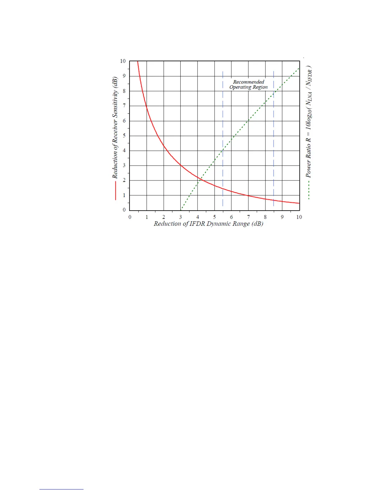
Figure 20 Trade-off Between Dynamic Range and Sensitivity
The solid red curve in on page 76 shows that these two variables interact
in a symmetric manner, so that any operating point (x,y) is always matched
by a dual operating point at (y,x). To understand the construction of this
plot, let N
IFDR
represent the stand-alone (terminated input) noise power of
the IFD over some bandwidth. Similarly, let N
LNA
represent the
LNA/Mixer thermal noise power over that same bandwidth, and after
amplification by all RF and IF stages. N
IFDR
is primarily due to the
quantization noise that is introduced by the A/D converter, whereas N
LNA
has its origins in the fundamental thermal noise of the receiving system.
The reduction of receiver sensitivity is the amount by which the LNA
thermal noise is increased over the original level established by the front-
end components:
Similarly, the reduction of RVP900 dynamic range is the amount by which
the IFDR quantization noise is increased over its stand-alone value:
 Loading...