Wiring an internal sounder
Installation & Configuration Manual
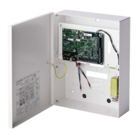
10.7 Wiring an internal sounder
To wire an internal sounder to the SPC controller connect the IN+ and IN–
terminals directly to the 12 V sounder input.
Internal sounder wiring (12 V)
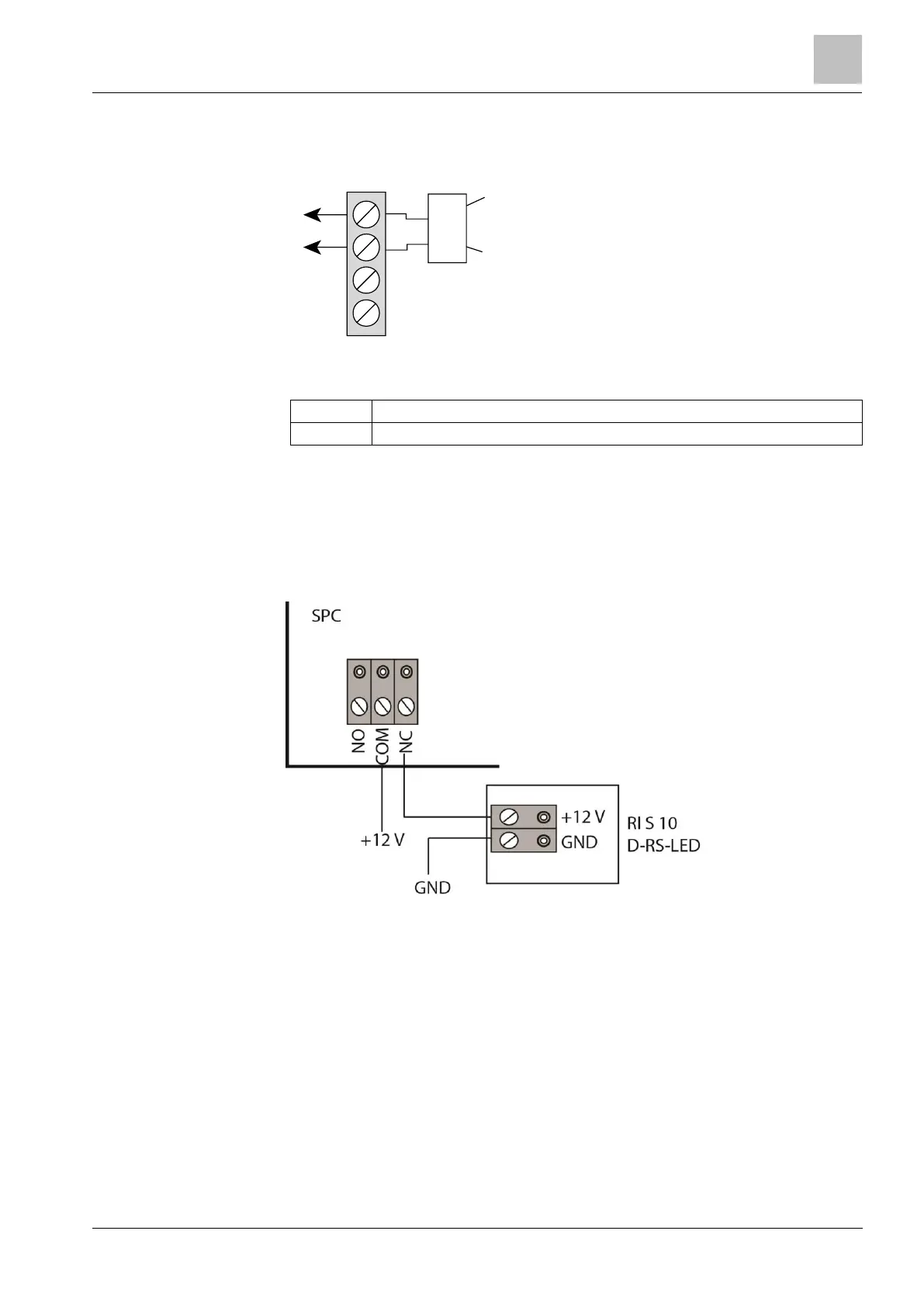
10.8 Wiring Glassbreak
SPC supports the RI S 10 D-RS-LED glassbreak interface in combination with
GB2001 glassbreak detectors.
The following diagram shows how the glassbreak interface is wired to the SPC
controller for power, or to an 8-in/2-out expander:
For information on wiring the glassbreak interface to a zone, see the product-
specific documentation.
For information on wiring the glassbreak sensors to the glassbreak interface, see
the product-specific documentation.
10.9 Installing plug-in modules
2 modems (PSTN or GSM) may be installed on the controller board to increase
functionality. The picture below shows the 2 slots available for each modem, the
primary (left) slot and the back-up (right) slot.
If both modem slots are available, always install the plug-in module in the primary
slot; the system always attempts to make PSTN or GSM calls on a modem
installed on the primary slot before attempting to use the back-up slot.