Installation & Configuration Manual
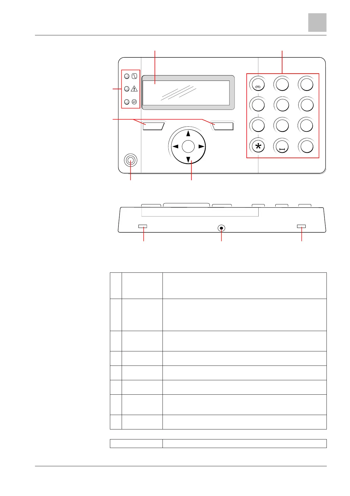
LCD keypad
The keypad display (2 lines x 16 characters) shows all alert and warning
messages and provides a visual interface for programming the system
(engineer programming only). The display can be adjusted for contrast and
under which conditions the backlight comes on.
Alphanumeric keypad allow for both text and numeric data entry during
programming. Alphabetic characters are selected by applying the appropriate
number of key presses. To switch between upper and lower case characters,
press the hash (#) key. To enter a numeric digit, hold down the appropriate
key for 2 seconds.
The leverage access tabs provide access to the keypad back assembly clips.
Users can unhinge these clips from the front assembly by inserting a 5mm
screwdriver into the recesses and pushing gently.
Back assembly
securing screw
This screw secures the front and back assemblies on the keypad. This screw
must be removed to open the keypad.
The LED status indicators provide information on the current status of the
system as detailed in the table below.
The left and right soft function keys are context sensitive keys to navigate
through menus/programming.
Proximity device
receiver area
If the keypad has been fitted with a proximity device receiver (see page
[➙ 343]), users should present the Portable ACE Fob to within 1 cm of this
area to SET/UNSET the system.
Multi-functional
navigation Key
The multi-functional navigation key in combination with the keypad display
provides an interface for programming the system.
4
ghi
5
jkl
6
mno
7
pqrs
8
tuv
9
wxyz
2
abc
3
def
#
0
1
ok
1
2
34
5
6
7
8
3