Assembly
1. Apply clean engine oil to piston pin, piston pin bosses,
and upper connecting rod bearing.
NOTE: For the longest service life, preserve existing wear
patterns by installing parts in their original locations.
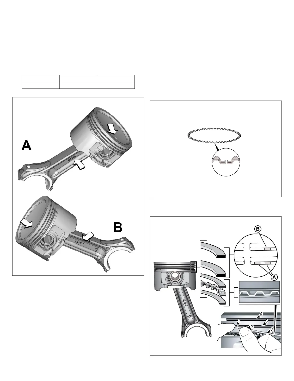
2. Place piston over small end of connecting rod, so that the
locating dot on the piston crown is on the same side as:
Cylinder 1 OUT-1 rod stamp See B in Figure 124.
Cylinder 2 OUT-2 rod stamp See A in Figure 124.
124
NOTE: When assemblies are installed in the crankcase,
cylinder 1 rod OUT-1 stamp and cylinder 2 rod OUT-2 stamp
will be visible through the crankcase cover opening.
3. Insert piston pin through piston pin bore and upper
connecting rod bearing. Push pin until it contacts
opposite pin boss.
NOTE: Do not reuse piston pin lock ring after it has been
removed. The lock ring may weaken or become distorted
during removal causing it to break or dislodge during engine
operation.
4. Install new piston pin lock ring into pin bore groove,
so that end of the lock ring is 90° from the pick lock
groove. Exercise care to avoid kinking, stretching, or
distorting lock ring. Verify that lock ring is fully seated in
the groove.
5. Use compressed air to remove any dirt or dust that may
have settled in the oil drain back holes and piston ring
grooves.
6. Apply clean engine oil to three piston ring grooves.
7. Install the oil control ring into the bottom ring groove.
Proceed as follows:
1. Install expander spring, so that the gap ends point
toward the piston crown (see Figure 125).
125
2. Spiral bottom oil rail into space below expander
spring (see Figure 126).
126
3. Spiral top oil rail into space above expander spring.
102 vanguardpower.com
 Loading...