Engine Wiring Harness Diagram
EFI and EFI-ETC Engine
Refer to theEFI and EFI-ETC Diagnostic Manualthat corresponds to your engine for pin-outs and diagnostic troubleshooting
of the engine wiring harness.
Carbureted and Gaseous Engines
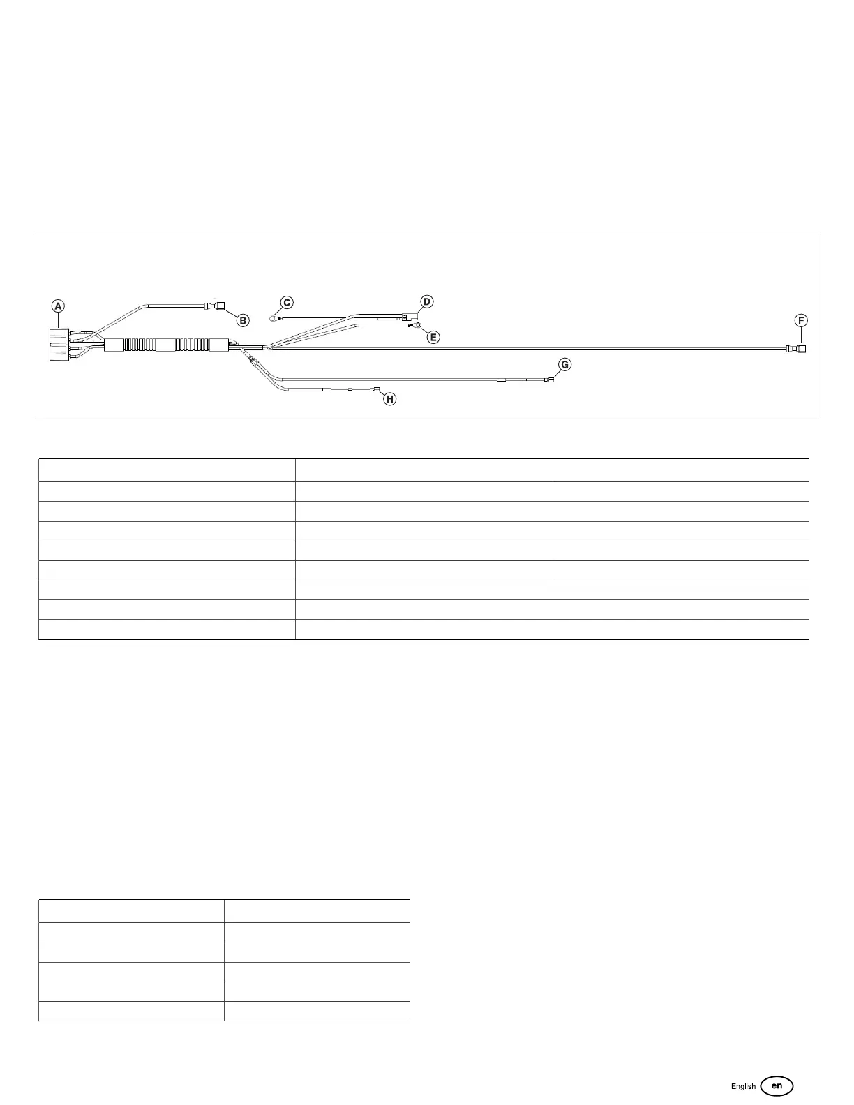
Your engine model may be fitted with additional equipment or lack components which may alter the appearance of the wire
harness. Figure 28 shows a typical wire harness forcarburetor equipped engines. Your engine may vary.
28
Carbureted Engine Wire Harness
Harness Connector Component Wire Color
Connector A Engine harness to equipment harness connector Black connector
Connector B Starter Solenoid Yellow Wire
Connector C Ground Wire Brown Wire
Connector D Anti-Afterfire Solenoid or Fuel Cut-Off Gray Wire and Brown Wire
Connector E Ground Wire Brown Wire
Connector F Oil Pressure Switch Green Wire
Connector G Ignition Armature Black Wire
Connector H Ignition Armature Black Wire
Carbureted and Gaseous Engine Wire Harness
Connector Pin-Out
The style and configuration of the engine-to-equipment
harness connector is determined by your engine's model,
trim, and type. The table that follows can be used as a
general guide to aid in the diagnostics and pin-out of the
engine harness connector.Component wire colors are
generally consistent across all engine models, trims, and
types, but care must be taken to independently confirm that
the connector wire matches the component wire.
Carbureted Engine Wire Harness Connector Pin-
OutIdentification
Component Wire Color
Ground Wire Brown
Ignition Wire Black
Oil Pressure Switch Green
Starter Solenoid Yellow
Fuel Solenoid Gray
41
 Loading...