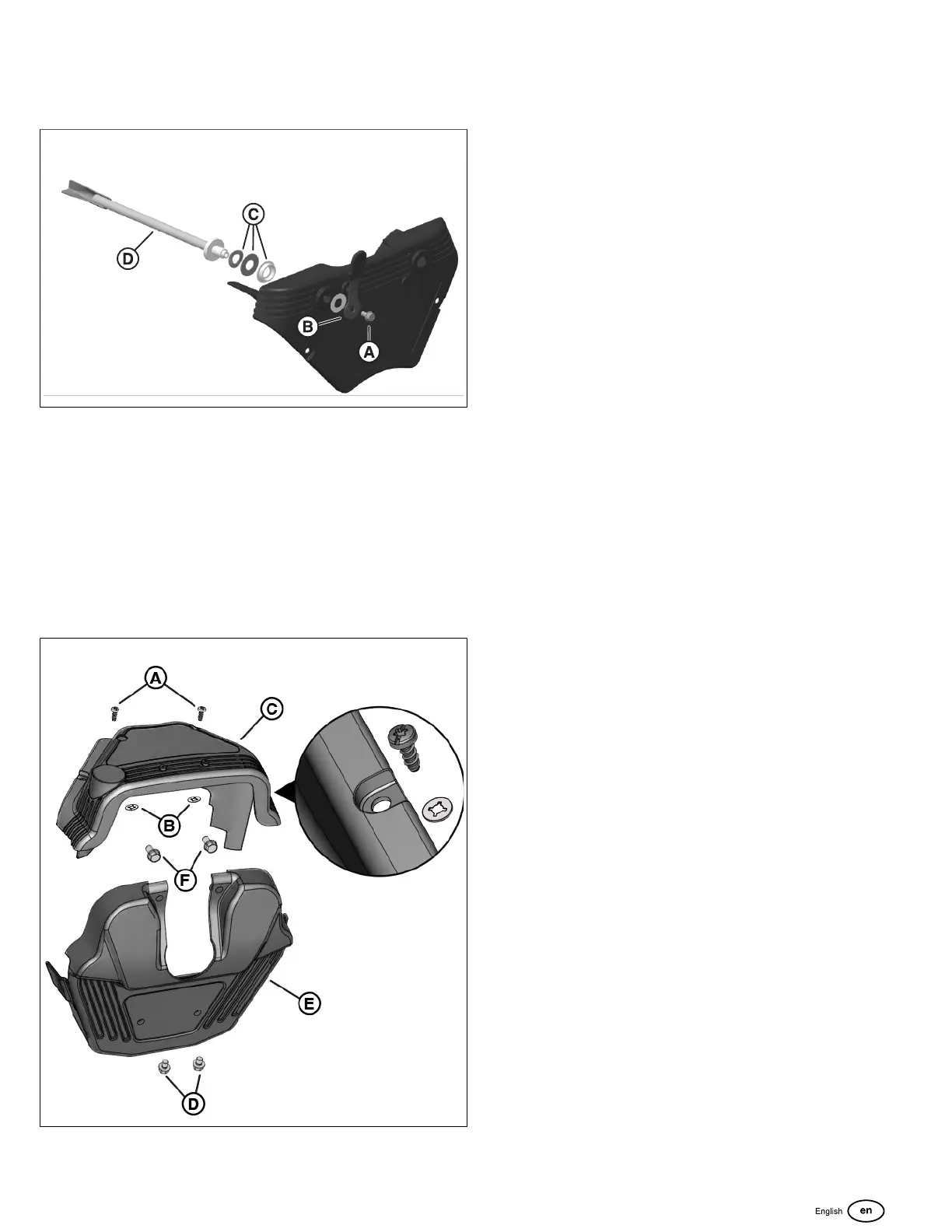
4. If equipped with a manual rotary throttle lever, install
the throttle lever (B, Figure 216) with fastener (A) and
washer stack (C) to the throttle shaft (D). Tighten to 90
lb-in (10.2 Nm).
216
5. Install the key switch cover (C, Figure 217)onto the
engine atop the blower housing.
6. Connect the choke rod to the speed control bracket by
inserting the end of the rod into the bushing hole (A,
Figure 215). Attach the retaining clip to the choke rod.
7. Connect the throttlecontrol shaft (D, Figure 216)to
the speed control bracketby pushing the shaft into the
bracket groove until captured.
8. Start by hand the 2 cover fasteners and retaining
washers (A-B, Figure 217). Tighten to 30 lb-in (3.4 Nm).
217
Intake Elbow Cover
1. If equipped, connect MIL/tachometer/hourmeter harness
connector to component connector on the back of the
cover.
2. Install air intake elbow cover (E, Figure 217)atop
the engine. Align the mounting holes to the threaded
mounting holes of the support brackets.
3. Start by hand the 2 cover fasteners that connect the
cover to the air cleaner bracket (F). Tighten to 90 lb-in
(10.2 Nm).
4. Start by hand the 2 cover fasteners that connect the
coverto the fuel pump module bracket(D). Tighten to 90
lb-in (10.2 Nm).
155
 Loading...