175
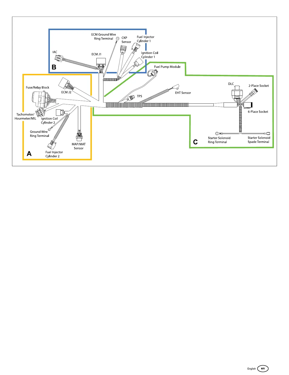
Wire Harness - EFI-ETC
The instructions for the installation of the wiring harness for
EFI and EFI-ETC engines can be used as a stand-alone
instruction for the wiring harness on an assembled engine OR
in conjunction with the assembly process of a disassembled
engine.
If you are installing the engine wiring harness as a part of
the assembly process of a disassembled engine, reserve the
instructions to connect the harness to various components
until those components have been assembled on the engine.
1. See inset of Figure 177.Starting with the main vehicle
connector and ending with the fuse/relay block, feed
branches ofwire harness down through opening next to
air block plate.
2. Rotate air block plate in a clockwise direction and install
Phillips screw to fasten plate to crankcase. Tighten screw
to 18 lb-in (2 Nm).
3. Connect ECM connector (R, Figure 176).
4. Install Phillips screw to fasten ECM ground wire ring
terminal (S) to throttle body. Tighten screw to 18 lb-in (2
Nm). If loosened or removed, install hex nuts onto two
studs to secure air intake elbow. Tighten nuts to 90 lb-in
(10.2 Nm).
5. InstallPhillips screw to fasten engine ground wire ring
terminal (T) to crankcase boss. Tighten screw to 45 lb-in
(5 Nm).
6. Install anchor of fir tree styleclip (Q,Figure 177)
capturing MIL, ECM, and ground wire ring terminal
conduit into hole in intake manifold boss next to air
cleaner bracket stud.
7. Running conduit between intake manifold and fuel rail,
connect cylinder 2 fuel injector connector (P, Figure 176).
Push in white secondary lock. If removed, install fuel
injector cap screw and tighten to 110 lb-in (12.4 N-m).
8. Running conduit between intake manifold and fuel rail,
connect cylinder 1 fuel injector connector (N). Push
in white secondary lock. Install anchor of fir tree style
clip (O,Figure 177) into hole in boss at top of intake
manifold. Ifremoved, install fuel injector cap screw and
tighten to 110 lb-in (12.4 Nm).
9. Connect cylinder 2 ignition coil connector (M, Figure
176)at top of intake manifold. Push in red secondary
lock.
10. Connect cylinder 1 ignition coil connector (L.Figure 177).
Push in red secondary lock. Install anchor of rosebud
style clip into hole in boss at bottom of intake manifold.
Install two screws to fasten ignition coil to intake manifold
bosses, if removed. Tighten screws to 30 lb-in (3.4 Nm).
11. Connect CKP sensor connector (K, Figure 176).
135
 Loading...