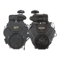
Testing Alternator Output
20 Amp Regulated Alternator
Output Test - 20 Amp Alternator
1. Obtain a digital multimeter. See Special Tools Listin this
section.
2. Disconnectthe stator wire harness from the voltage
regulator.
3. Set-up the digital multimeter by inserting the RED test
lead into the volt/ohm receptacle of the meterand the
BLACK test lead into the COM receptacle of the meter.
4. Select AC VOLTS on the multimeter.
5. Connect the RED and BLACK test lead probes onto the
output terminals of thestator.
NOTE: Test lead probes may be attached to either terminal.
Alligator styleprobe clips may be necessary to maintain a
positive connection.
6. Start the engine.
7. With the engine running at 3600 RPM output should be
no less than 30 Volts.
Regulator-Rectifier Test- 20 Amp
NOTE: Make sure that the regulator is securely mounted
to the engine. The regulator will not function unless it is
grounded to the engine. When testingthe regulator for
amperage output, a 12 volt battery with a minimum charge of
5 volts is required. There will be no output if battery voltage is
below 5 volts.
2 tests must be performed to confirm a properly operating
voltage regulator. A DC Amp test and a DC Voltagetest.
1. If previously disconnected, re-connect the stator wire
harness to the regulator.
2. Obtain a digital multimeter with inductive clamp. See
Special Tools List in this section.
3. Place the inductive clamp of the multimeter over the RED
regulator output wire.
4. On the multimeter, select theDC Amps position on the
selector wheel.
5. Start the engine.
6. With the engine running at 3600 RPM, the output should
be 1-20 Amps.
NOTE: Amp reading is dependent upon battery voltage and/
or current draw on the system.
7. See steps 1-3 of the previous test.
8. On the multimeter, select the DC Voltsposition on the
selector wheel.
9. Start the engine and allow to run for 15 minutes.
10. With the engine running at 3600 RPM, the output should
be between 13.9 and 14.5 VDC.
20/50 Amp Regulated Alternator
Output Test - 20/50 Amp Alternator
1. Obtain 2 digital multimeters. See Special Tools Listin this
section.
2. Disconnectthe stator wire harness from the voltage
regulator.
3. Set-up the digital multimeters by inserting the RED test
lead into the volt/ohm receptacle of the meterand the
BLACK test lead into the COM receptacle of the meter.
4. Select AC VOLTS on the multimeters.
5. Connect the RED and BLACK test lead probes onto the
output terminals of thestator.
NOTE: Test lead probes may be attached to either terminal.
Alligator styleprobe clips may be necessary to maintain a
positive connection.
6. Start the engine.
7. With the engine running at 3600 RPM output should be
45-50Volts on eachstator output.
Regulator-Rectifier Test - 20/50 Amp
NOTE: Make sure that the regulator is securely mounted
to the engine. The regulator will not function unless it is
grounded to the engine. When testingthe regulator for
amperage output, a 12 volt battery with a minimum charge of
5 volts is required. There will be no output if battery voltage is
below 5 volts.
2 tests must be performed to confirm a properly operating
voltage regulator. A DC Amp test and a DC Voltagetest.
1. If previously disconnected, re-connect the stator wire
harness to the regulator.
2. Obtain a digital multimeter with inductive clamp. See
Special Tools Listin this section.
3. Place the inductive clamp of the multimeter over the RED
regulator output wire.
4. On the multimeter, select theDC Amps position on the
selector wheel.
5. Start the engine.
6. With the engine running at 3600 RPM, the output should
be 3-50 Amps.
NOTE: Amp reading is dependent upon battery voltage and/
or current draw on the system.
7. See steps 1-3 of the previous test.
8. On the multimeter, select the DC Voltsposition on the
selector wheel.
9. Start the engine and allow to run for 15 minutes.
10. With the engine running at 3600 RPM, the output should
be between 13.9 and 14.5 VDC.
38 vanguardpower.com

 Loading...