2. Install oil scavenge hose fitting and hose as follows:
A. Apply a light film of clean engine oil to new o-ring (C)
of oil scavenge pump hose fitting (D). Install o-ring
onto fitting.
NOTE: Verify that old o-ring is not present in the
crankcase cover bore. Inadvertently stacking old and
new o-rings will result in oil leaks.
B. Install oil scavenge pump hose fitting into crankcase
cover bore closest to the cylinder heads, and hand
tighten until snug. Tighten hose fitting to 215 lb-in
(24.3 Nm).
C. Install oil scavenge hose connector (with redclip
lock)onto fitting. Push inclip lockto secure.
3. Install crankcase ventilation hoseconnector(with
blueclip lock)onto fitting. Push inclip lock to secure.
4. Install oil supply check valve, hose fitting, and hose as
follows:
A. Install oil supply check valve (E) into crankcase
cover bore farthest from the cylinder heads. Tighten
check valve to 375 lb-in (42.4 Nm).
B. Apply a light film of clean engine oil to new o-ring (F)
of oil supply pump hose fitting (G).Install o-ring onto
fitting.
NOTE: Verify that old o-ring is not present in the
check valve bore. Inadvertently stacking old and new
o-rings will result in oil leaks.
C. Install hose fitting into check valve and tighten to 325
lb-in (36.7 Nm).
5. Prime oil supply pump as follows:
NOTE:Failure to prime oil supply gerotor pump will
result in air pockets in the lubrication system and can
lead to catastrophic engine damage.
A. If available, obtain green rubber cap used to keep
dust and dirt out of fitting during shipping. Install
rubber cap onto fitting to act as an oil seal during
priming.
B. Obtain standard oil can with a pointed nozzle. Verify
that nozzle is clean of dirt and grit, and then push
through rubber cap.
C. Add 3 ounces (88.7 ml) of oil. Remove and discard
rubber cap.
D. Install oil supply hose connector (with greenclip
lock) onto fitting. Push inclip lock to secure.
Oil Pressure Switch
1. Thoroughly clean the threads of the oil pressure switch to
remove any dirt or debris.
2. Snuglywrap thread sealing tape around the threads of
the switch 2-3 times in a counter-clockwise direction.
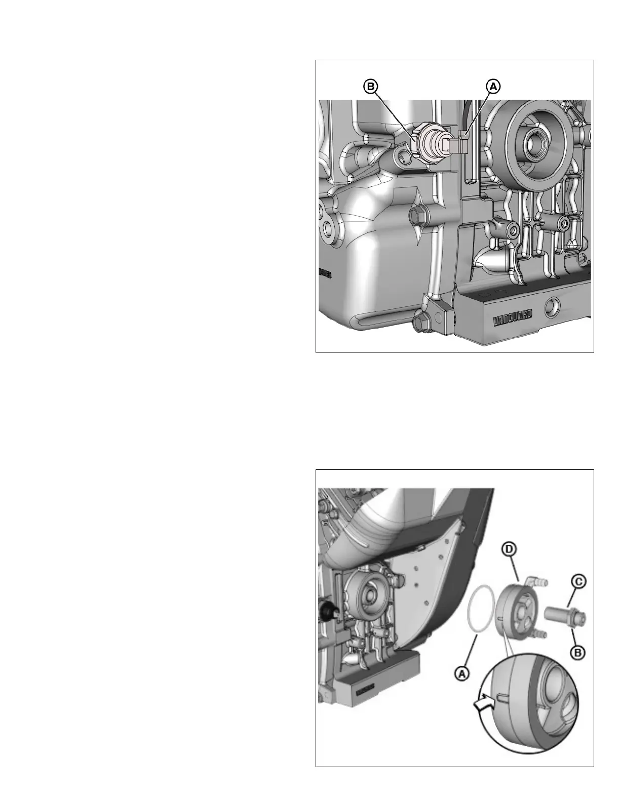
3. Start by hand the switch (B, Figure 225)into the
crankcase. Tighten to 15 lb-in (1.7 Nm).
225
4. Connect the harness spade connector (A) to the switch
spade contact.
Oil Diverter Valve and Drip Tray
1. Inspect o-ring(A, Figure 226)in diverter groove for
cuts, tears, or general deterioration. Install new o-ring, if
necessary.
226
160 vanguardpower.com
 Loading...