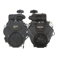
Wire Harness- EFI
The instructions for the installation of the wiring harness for
EFI engines can be used as a stand-alone instruction for the
wiring harness on an assembled engine OR in conjunction
with the assembly process of a disassembled engine.
If you are installing the engine wiring harness as a part of
the assembly process of a disassembled engine, reserve the
instructions to connect the harness to various components
until those components have been assembled on the engine.
1. PositionEFI wire harness at top of intake manifold
separating conduit and connectors into three groups as
shown in Figure 175.
2. See section C of Figure 175. Feed wire harness
connectors and conduit down through air block mounting
plate opening to area below intake manifold.
3. See section B of Figure 175. On cylinder 1 side of
engine, proceed as follows:
1. Connect ECM J1 connector.
2. Slide fastener through ECM flange (Grey ECM J1
connector side) and ground wire ring terminal. Start
fastener into ECM/fuse block bracket and tighten to
44 lb-in (5 Nm).
3. Connect fuel injector connector. Push in green
secondary lock to secure.
4. Install new cable strap through ignition coil wire
harness socket connector, install over inside ignition
coil mounting boss, and connect connector.
5. Connect CKP sensor connector.
6. Connect IAC connector.
4. See section A of Figure 175. On cylinder 2 side of
engine, proceed as follows:
1. Install fastener for fuse block cover to ECM/fuse
block bracket. Tighten fastener to 87 lb-in (9.8 Nm).
2. Connect MAP/MAT sensor connector. Push in red
secondary lock to secure.
3. Connect fuel injector connector. Push in green
secondary lock to secure.
4. Install new cable strap through ignition coil wire
harness socket connector, install over inside ignition
coil mounting boss, and connect connector.
5. Install ground wire ring terminal to cylinder boss and
start fastener. Tighten fastener to 29 lb-in (3.3 Nm).
6. Connect ECM J2 connector.
5. See section C of Figure 175. Proceed as follows:
1. Connect TPS connector.
2. Connect fuel pump module connector. Push in grey
secondary lock to secure.
3. Orient EHT sensor with end rotated against tab on
cylinder 1. Install fastener and tighten to 44 lb-in (5
Nm).
4. Connect starter solenoid ring and spade terminals.
5. Connect 2- and 6-place (or single 8-place) engine to
chassis connectors.
6. Install 2 fasteners (with captive washers) to fasten air
block mounting plate to cylinder. Alternately tighten
screws to 29 lb-in (3.3 Nm).
7. Install new cable strap around intake manifold between
air block mounting plate and inside cylinder 2 ignition coil
mounting boss capturing convoluted tubing of ignition coil
and fuel injector.
8. Install new cable strap around intake manifold between
air block mounting plate and inside cylinder 1 ignition coil
mounting boss capturing fuel injector, ignition coil and
CKP sensor conduit.
134 vanguardpower.com

 Loading...