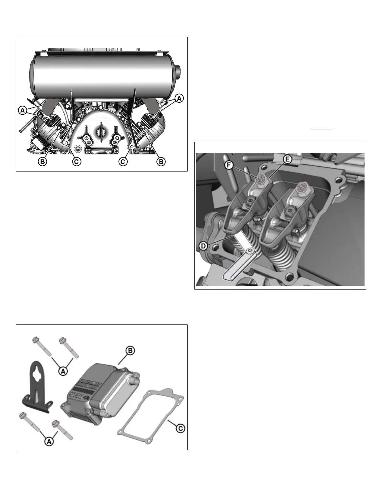
9. Verify that exhaust manifold to cylinder head screws (A,
Figure 13) are tightened to 195 lb-in (22 Nm).
13
10. Verify that muffler bracket to cylinder screws (B) are
tightened to 195 lb-in (22 Nm).
11. If equipped, verify that muffler support bracket nuts to
crankcase cover studs (C) are tightened to 195 lb-in (22
Nm).
12. Install spark plug wires onto spark plug terminals.
Check/Adjust Valve Clearance
NOTE: Check valve clearance with the engine cold.
1. Remove spark plug wires from spark plug terminals.
2. Thoroughly clean area around spark plugs to keep dust
and dirt out of the combustion chambers.
3. Remove spark plugs from cylinder heads. See Check/
Gap/ReplaceSpark Plug.
4. Remove the 4 fasteners (A,Figure 14)to release valve
covers (B) from cylinderheads.
14
5. Remove and discard valve cover gaskets (C).
6. Move the piston of the first cylinder to Top Dead Center
(TDC) of the compression stroke. Proceed as follows:
A. While rotating flywheel end of crankshaft by hand
in the direction of engine rotation, watch the rocker
arms to determine the action of the valves. After
the exhaust valve closes, the intake valve begins to
open.
B. When the intake valve closes (so that both valves
are closed with the rocker arms loose), insert a
wooden dowel through the spark plug hole until
seated at the top of the piston.
C. Rotate engine in the same direction until the piston
pushes the wooden dowel to its highest point. This is
TDC of the compression stroke.
7. Insert feeler gauge between rocker arm and exhaust
valve stem(D, Figure 15). Verify that exhaust valve
clearance is 0.007-0.009 inches (0.18-0.23 mm).
15
8. If adjustment is necessary, proceed as follows:
A. Obtain the Valve Adjustment Set. See SECTION 3 -
TROUBLESHOOTING - Special Tools List.
B. Place 13 mm hexsocketover lock nut(E).
C. Insert T-40TORXbit through hole in socket tool to
engage adjuster screw(F).
D. While holding adjuster screw to prevent rotation,
loosen lock nut with socket, and then slightly turn
adjuster screw in a clockwise or counter-clockwise
direction (to either reduce or increase the valve
clearance, respectively).
E. Holding adjuster screw to prevent rotation, rotate
socket to tighten lock nut.
F. Remove tools and use feeler gauge to check valve
clearance. Repeat steps as necessary until proper
valve clearance is obtained.
G. Holding adjuster screw to prevent rotation, tighten
lock nut to 105 lb-in (11.8 Nm). Check valve
clearance one more time to verify that adjusting
screw did not move when lock nut was tightened.
20 vanguardpower.com
 Loading...