EasyManua.ls Logo

VAT 651 Series User Manual

VAT 651 Series
99 pages
To Next Page IconTo Next Page
Page #1 background imageLoading...
Page #1 background image
Installation, Operating &
Maintenance Instructions
605451EC Edition 2014-07-10
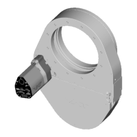
Pendulum control & isolation valve
with extended control range
with Logic interface
Series 651
DN 160–250 mm (I.D. 6“ - 10")
This manual is valid for the valve ordering number(s):
651 . . - . .GC- . . . . (1 sensor input)
651 . . - . .GE- . . . . (2 sensor inputs)
651 . . - . .AC- . . . . (1 sensor input / ±15V SPS)
651 . . - . .AE- . . . . (2 sensor inputs / ±15V SPS)
651 . . - . .HC- . . . . (1 sensor input / PFO)
651 . . - . .HE- . . . . (2 sensor inputs / PFO)
651 . . - . .CC- . . . . (1 sensor input / ±15V SPS / PFO)
651 . . - . .CE- . . . . (2 sensor inputs / ±15V SPS / PFO)
SPS = Sensor Power Supply PFO = Power Failure Option
configured with firmware 600P.1G.00.04, 600P.1G.00.05…08
Sample picture

Table of Contents

Questions and Answers:

VAT 651 Series Specifications

General IconGeneral
BrandVAT
Model651 Series
CategoryControl Unit
LanguageEnglish

Summary

Description of product

Product Identification

Details on how to identify the valve, including fabrication and order numbers.

Product Use

Explains the intended applications and limitations for this throttling pendulum valve.

Abbreviations Used

Lists common abbreviations like CPA, PFO, SPS, ADC found in the manual.

Related Documents

Lists other documents relevant to the product, such as data sheets and drawings.

Important Information

Highlights important statements requiring particular attention, often referring to other sections.

Technical Data

Control and Actuating Unit Data

Specifies electrical and power input requirements for the control unit.

Valve Unit Specifications

Details technical specifications for the valve unit, including pressure range and materials.

Safety

Compulsory Reading

Emphasizes the importance of reading and understanding safety information before operation.

Danger Levels

Defines different risk levels (Danger, Warning, Caution, Notice) and associated hazards.

Personnel Qualifications

Specifies the required qualifications for personnel working with the valve.

Safety Labels

Identifies safety labels and their locations on the valve.

Design and Function

Product Design

Illustrates the physical components and assembly of the valve unit.

Valve Functionality

Explains how the valve operates as a throttling element and for isolation.

Pressure Control System Overview

Provides a schematic and functional overview of the pressure control system.

Pressure Control System Principle

Details the operational principle of the pressure control system, including PID control.

Installation

Unpacking Procedure

Instructions for safely unpacking the valve and checking its contents.

Installation into the System

Guidelines and warnings for installing the valve into the vacuum system.

Installation Space Condition

Specifies the necessary clearance around the valve for installation and maintenance.

Connection Overview

Shows the system schematic and controller connection points for wiring.

Installation Procedure Steps

Step-by-step instructions for physically installing the valve into the vacuum system.

Tightening Torque Specifications

Provides torque values for mounting screws based on valve size and flange type.

Mounting with Centering Rings

Specific torque values and procedures for mounting with centering rings.

Mounting with O-ring in Grooves

Specific torque values and procedures for mounting with O-rings.

Admissible Forces

Defines the maximum axial and bending forces the valve body can withstand.

Requirements to Sensor Connection

Specifies requirements for connecting pressure sensors for optimal performance.

Electrical Connection

General warnings and guidelines for electrical connections to the valve.

Ground Connection Details

Recommendations for proper grounding of the valve controller to the system chassis.

Sensor Supply Concepts

Outlines the three alternative concepts for supplying power to the sensor(s).

+24 VDC Sensor Power Connection

Details wiring for connecting +24 VDC sensors via the controller or externally.

±15 VDC Sensor Power Connection (No SPS)

Wiring instructions for ±15 VDC sensors without the optional SPS module.

±15 VDC Sensor Power Connection (With SPS)

Wiring instructions for ±15 VDC sensors with the optional SPS module.

Service Port Connection

How to connect the valve to a computer via the RS232 service port.

Functions and Wiring

Explains logic interface functions and wiring for remote operation using digital signals.

Digital Inputs Configuration

Details the functions and pin assignments for digital inputs on the valve.

Digital Outputs

Describes the functions and pin assignments for the valve's digital outputs.

Analog Inputs and Outputs

Explains the analog inputs for setpoints and analog outputs for status readings.

Initial Operation

Outlines the necessary setup steps to enable the valve for pressure control.

Setup Procedure

Lists the sequence of steps required for initial valve setup and configuration.

Logic Interface Configuration

How to configure the logic interface for remote operation based on application needs.

Valve Configuration

How to adapt basic valve configuration to specific application requirements.

Sensor Configuration

How to adapt basic sensor configuration to specific application needs.

ZERO Function

How to compensate for sensor offset voltage and set pressure to zero.

LEARN Adaptive Control

How to adapt the PID controller to the vacuum system characteristics.

Pressure Control Configuration Options

Describes different pressure control configurations (Downstream, Upstream, Soft Pump).

Pressure Controller Setup

How to configure the pressure controller type (adaptive, fixed, soft pump).

Pressure Control Parameters

Details the parameters for different pressure control algorithms.

Pressure Control Algorithm

Explains the adaptive, fixed 1, fixed 2, and soft pump control algorithms.

Tuning of Control Performance

Guidance on adjusting control parameters to optimize valve performance.

Adaptive Control Tuning

Step-by-step guide to tune adaptive pressure control performance.

Gain Factor Adjustment

How to adjust the gain factor to affect stability and response time.

Sensor Delay Adjustment

How to adjust sensor delay to improve stability.

Setpoint Ramp Adjustment

How to adjust setpoint ramp time to improve pressure response.

Valve Speed Adjustment

How to adjust valve speed for optimal pressure control response.

Fixed PI Control Tuning

How to optimize P gain and I gain for fixed PI pressure control.

Soft Pump Control Tuning

How to optimize P gain for pressure control ramps during pump down.

Operation

Normal Operation

General description of the valve's operation in pressure or position control modes.

Local Operation

How to operate the valve using a computer or Service Box 2.

Remote Operation

How to operate the valve remotely using its logic interface.

Close Valve

Procedures for closing the valve locally or remotely.

Open Valve

Procedures for opening the valve locally or remotely.

Position Control

How the valve position is controlled based on the setpoint.

Pressure Control

How to prepare and perform pressure control operations.

Operation with 2 Sensors

How the valve operates with two pressure sensors for extended range.

Display Information

Explains the information displayed on the valve's panel during operation.

Power Up Display

Describes the initial display information shown when the valve powers up.

Operation Modes Display

Details the display codes for different operational modes and statuses.

Error Codes Display

Lists and explains error codes displayed on the valve panel.

Safety Mode Operation

How the valve enters and behaves in safety mode, e.g., during maintenance.

Service Indication

How the valve indicates when cleaning or an obstruction is present.

Operation during Power Up

Describes the valve's behavior and display during power up.

Behavior in case of Power Failure

Explains how the valve behaves during power loss, with and without PFO.

Operation Under Increased Temperature

Warnings and guidelines for operating the valve at elevated temperatures.

Compressed Air Pressure Drop Behavior

Describes the valve's reaction to a drop in compressed air pressure.

Trouble shooting

Maintenance

Maintenance Intervals

Information on recommended maintenance intervals and factors affecting them.

Maintenance Procedures

Outlines preventive maintenance tasks, including seal replacement and cleaning.

Replacement of Isolation Seals and Cleaning

Detailed steps for replacing isolation seals and cleaning the valve.

Replacement of Actuator Shaft Seals

Detailed steps for replacing actuator shaft seals.

Replacement of Option Board

Instructions for replacing or retrofitting option boards like SPS and PFO.

Retrofit / Replacement Procedure

General procedure for retrofitting or replacing electronic boards within the unit.

Repairs

Dismounting and Storage

Dismounting

Steps and precautions for safely dismounting the valve from the system.

Storage Guidelines

Recommendations for proper storage conditions to prevent product damage.

Packaging and Transport

Packaging Instructions

Guidelines for packaging the valve for return or transport.

Transport Recommendations

General advice on handling and transporting the product to prevent damage.

Disposal

Spare parts

Spare Parts Drawing

Diagram showing the components of the valve unit with numbered parts.

Valve Unit Spare Parts

Lists part numbers for seals, O-rings, and grease for the valve unit.

Control and Actuating Unit Parts

Lists part numbers for control units, option boards, and related kits.

Accessories

Lists part numbers for accessories like power supplies, cables, and software.

Appendix

Related product manuals