devices (e.g., Remote Pulser, printer, etc.). This equipment must be installed according to the applicable
installation document. For UL/cUL installations use Control Drawing number 331940-021 and for ATEX
Head installation.
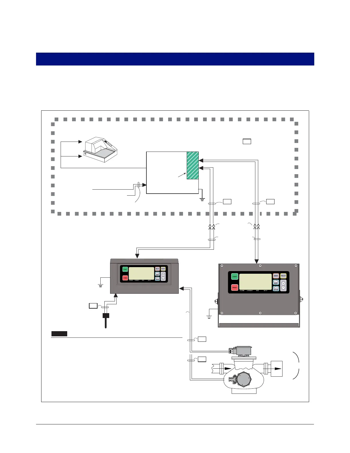
Figure 1. Example EMR4 truck Installation With 2 Display Heads And Optional Remote Pulser
DC voltage from vehicle's accessory
circuit - at fuse block or ACC position
of ignition switch
Display Head 1
(Meter 1)
Meter 2
Remote Display Head 2
Top mount
Remote Pulser
Front mount
Remote Pulser
TRUCK CAB
OUTSIDE TRUCK CAB
Data (RS-485)
Data (RS-485)
Power
Data
Power 12 Vdc
Power 12 Vdc
5 Vdc
Pulse Input
NON-HAZARDOUS
LOCATION
(RS-232)
Printer
Quick disconnect
fittings (optional)
Temp
Probe
EPSON TM295 SLIP
Customer supplied wiring
The following information is for general reference and is not
intended to replace recommended National Electric Code (NEC)
procedures. It is important for the installer to understand that
wiring located in Class I, Group D, Division 1 and 2 installations,
or Class I, Zone 0, Group IIA locations shall comply with the latest
appropriate articles found in the National Electric Code (NFPA
70).
Check continuity between the Display Head chassis and the IB
chassis through the vehicle fra
me. The resistance must be no
more than 1 Ohm.
24 Vdc
Truck ground
Max. cable length
35 ft. (10.6 m)
Max. cable length
1000 ft. (304.8 m)
HAZARDOUS LOCATION
OR
I.S.
I.S.
I.S.
I.S.
I.S.
I.S.
NOTE: Intrinsically safe wiring
(marked ) shall be installed
in accordance with Article 504-20
of the NEC, ANSI/NFPA 70.
Intrinsically
safe barrier
Interconnection
Box
12 AWG U.S. (4mm
2
E.U.)
Barrier Ground
(See Notice 2)
Input Rating: 10-28 Vdc, 4 A
1.
See
Notice 2.
See
Notice 2.
2.
NOTICE
NOTICE

 Loading...


