20
EMR
3
- Truck Installations
EMR4 Truck Installation Neptune Flow Meter Installation
1. Remove and put aside the four mounting bolts holding the meter register assembly to the meter adapter
mounting flange. Remove the existing mechanical register.
2. Remove the cover, P/N 86665-000, from the mechanical register’s lever arm assembly.
3. Remove the lever arm assembly from the meter. Keep the locking pin (P/N 86661-001).
4. Remove and put aside the four mounting bolts holding the meter register assembly to the spacer (these bolts
may be needed for reassembly).
5. Remove the mechanical meter register and the (4) temperature compensator bolts. Take out the compensator
gear assembly.
6. Keep the main case cover (P/N 400081-002) and the spacer (P/N 86711-000) in place. Clean off the top of
the spacer.
7. Set the V-R Adapter (P/N 333746-001) on top of the spacer and mount it using (4) bolts (P/N 510500- 325)
with lockwashers [see Figure 14].
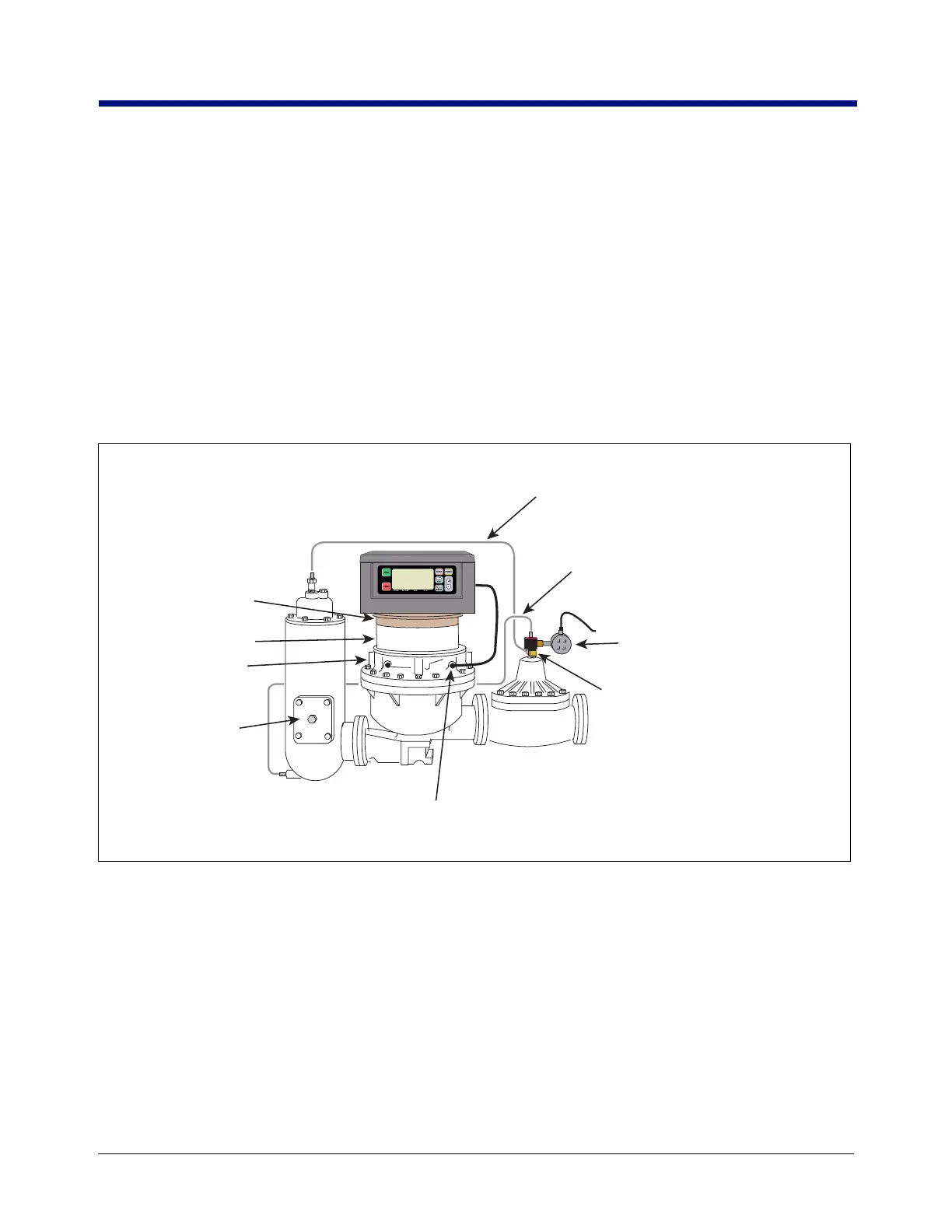
Figure 14. Example Of Temperature Probe Installation In Main Case Cover
8. Notice the type of coupling connecting the register/preset to the meter adapter input shaft.
9. Remove the four cover bolts of the Display Head and lift off the cover. Put the cover and bolts aside.
10. Look at the base of the Display Head. Locate the Encoder Drive Spring (see Figure 20). Pull/slide the encoder
spring off of the encoder shaft.
11. The end of the encoder input shaft projecting out of the bottom of the Display Head has a small cotter pin
inserted in it to keep it from sliding up into the Display Head and a washer (P/N 011071-933). Remove this
cotter pin. Remove the encoder input shaft and washer (you will reuse this washer).
12. Get the 4” (101.60 mm) long encoder input shaft, the 0.010” and 0.005” thick washers, the retaining ring, the
groove pin, and the coupling from the installation kit.
Strainer cover
Neptune Adapter Ring
used for retrofitting Neptune
meters with mechanical
temperature compensation
Optional Display Head temperature
probe shown installed in the V-R thermowell
(remove plastic plug from thermowell)
Main case cover
Neptune Spacer
758-14.eps
Reinforced flexible metal hose rated for
LPG use w/ 3/8" NPT male fittings each
end. Attach one end to Port 1 of 3-way
valve and other end to vapor eliminator
Reinforced flexible metal hose rated for
LPG use w/ 3/8" NPT male fittings each
end. Attach one end to Port 3 of 3-way
valve and other end to line pressure
3/8" NPT brass elbow w/ male fittings
each end. Attach one end to Port 2 of
3-way valve
and other end to differential
valve fitting.
Attach 1/2" NPT nipple and junction box
to wiring port of 3-way valve. Route
wiring to IB box

 Loading...


