Display Head installation.
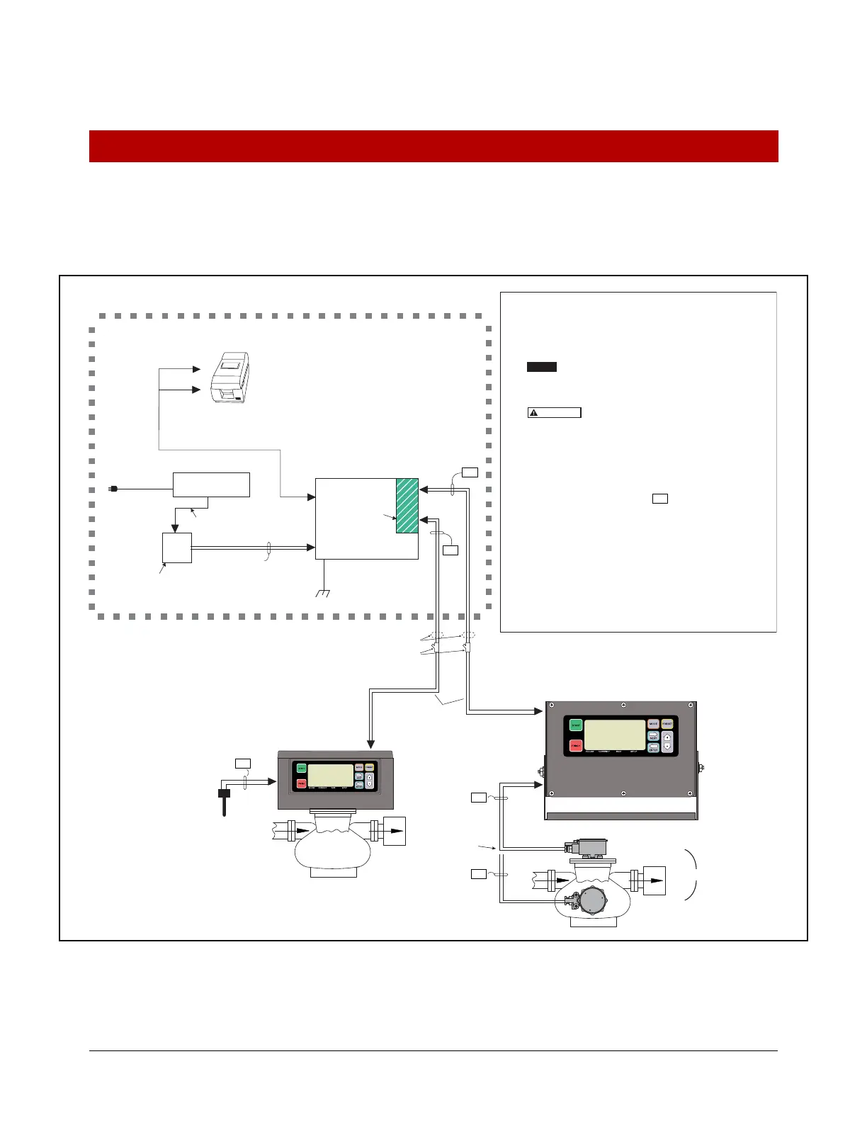
Figure 36. Example Terminal Fueling Depot Installation With 2 Display Heads And Optional Remote Pulser
TERMINAL
OFFICE
HAZARDOUS
LOCATION
NON-HAZARDOUS
LOCATION
Rigid conduit
Interconnect
Box
Printer
Data
(RS-232)
Intrinsically
safe barrier
Data (RS-485)
Data (RS-485)
Power
Power
Power
120 or 240Vac
line cord
Seal-off
UL approved 120W
isolated secondary
Input Rating: 10–28 Vdc, 5 A
120 or 240Vac line
12 Vdc
Power
Supply
Customer supplied
wiring & rigid conduit
24 Vdc
Temp
Probe
UPS
AC Power Protector
The following information is for general reference and is not intended
to replace recommended national electric code (nec) procedures. it is
important for the installer to understand that wiring located in Class I,
Group D Division 1 and 2 installations or Class I, Zone 0, Group IIA
locations shall comply with the latest appropriate articles found in the
National Electric Code (NFPA 70).
This is a control drawing only and doe
s not reflect the actual
locations of conduit entry. In Installation and use of this product,
comply with the national electrical code; Federal, State and Local
Codes.
FAILURE TO COMPLY WITH THE FOLLOWING
WARNINGS AND SAFETY PRECAUTIONS COULD CAUSE
DAMAGE TO PROPERTY, ENVIRONMENT, RESULTING IN
SERIOUS INJURY OR DEATH.
The Display Head must never be operated unless the front cover
and wiring shield are closed and properly sealed over the barrier
terminals in the intrinsically safe area of the Interconnect Box.
1. Intrinsically safe wiring (marked ) shall
be installed in
accordance with Article 504-20 of the NEC, ANSI/NFPA 70.
2. In the non-intrinsically safe compartment of the Interconnect Box,
connect the #12 AWG (4mm
2
) or larger diameter barrier wire to a
ground lug.
3. To maintain intrinsic safety, display head to interconnect box
wiring must be run in dedicated conduit. Maximum cable length is
1,000 feet (304.8 M).
4. Display Head must be connected to earth ground
through its mounting screws.
Display Head 1
(Meter 1)
EPSON U220 ROLL
Meter 2
Remote
Display Head 2
Top mount
Remote Pulser
Front mount
Remote Pulser
5 Vdc
Pulse Input
Max. Remote
Pulser cable
length 35 ft.
(10.6 m)
Meter 1
OR
Max. cable length
1000 ft. (304.8 m)
I.S.
I.S.
I.S.
I.S.
I.S.
I.S.
Connected to
Earth Ground
12 AWG U.S. (4mm
2
E.U.)
Barrier Ground
NOTICE
WARNING

 Loading...


