21
EMR
3
- Truck Installations
EMR4 Truck Installation Neptune Flow Meter Installation
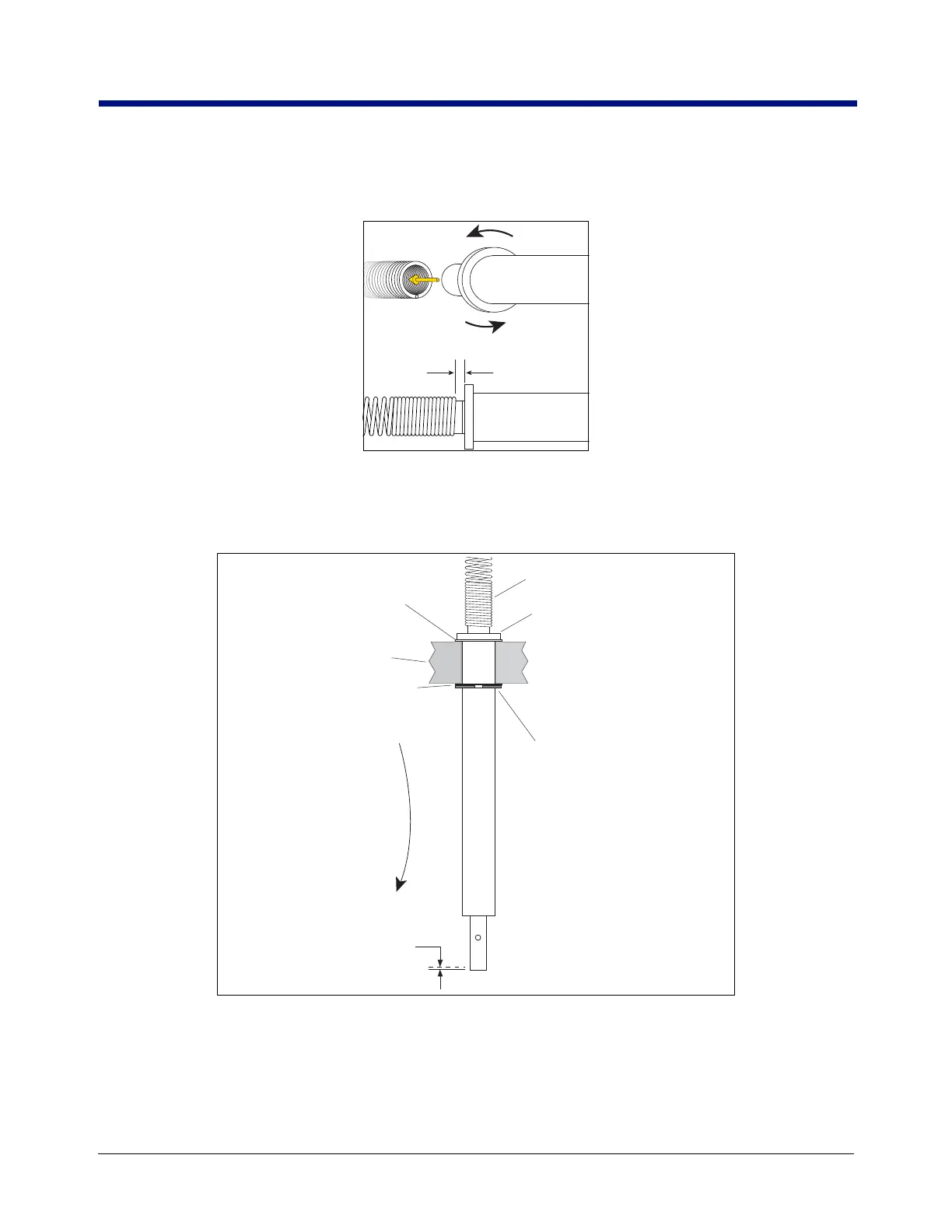
13. With the encoder spring in your left hand and the input shaft in your right, orient the input shaft as shown in
Figure 15, then rotate the input shaft in a counter-clockwise direction as you ‘screw’ it into the spring until the
flange on the input shaft is about 1/8” from the end of the spring.
Figure 15. Screwing Input Shaft CCW Into Encoder Spring
14. Assemble the new shaft, the 0.010” washer you removed from the Display Head shaft in the previous step, the
0.005” washer, and the retaining ring in the Display Head base as shown in Figure 16. If the 0.010 - 0.015”
end play is exceeded, remove the retaining ring and replace the 0.005” washer with the 0.010” washer.
Figure 16. Assembling Neptune Adapter Shaft Group To Display Head
15. Carefully bend the encoder spring over to the encoder shaft and push the open spring end onto the shaft.
Work the spring onto the shaft until it is about 1/8” from the pulse encoder (Figure 17).
Display Head Base
Encoder spring
0.010" (0.25 mm)
Washer -reused
0.005" (0.127 mm) washer
from kit (if necessary use
0.010" washer from kit instead
to get desired end play)
Retaining ring
from kit
0.010 - 0.015"
(0.25 - 0.38 mm)
endplay
4" (101.6 mm) encoder input
shaft from kit
758-15.eps

 Loading...


