45
EMR
3
- Truck Installations
EMR4 Terminal & Fueling Depot Installation Power Conditioning Requirements
Power Conditioning Requirements
Two separate electrical components are installed in EMR4 terminal - fueling depot applications - an uninterruptable
power supply (UPS) (recommended) and a +24 Vdc power supply (required). Veeder-Root recommendations for
this equipment are discussed below.
1. UPS (Uninterrupted Power Supply) - Optional
Veeder-Root recommends the Tripp Lite UPS model BC PERS450 (or equivalent) for up to 15 minutes of
power backup to the +24 Vdc power supply. For pricing or additional information, you can phone Tripp Lite
customer support or visit their website at www.tripplite.com/support/bcpers450.
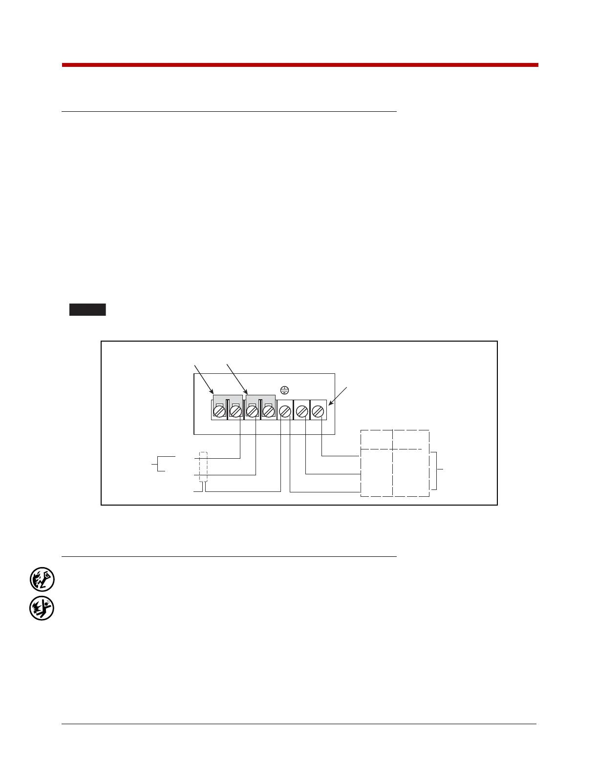
2. Power supply - UL approved, 120 watt minimum, AC to DC - Two Vendors Recommended: Digi-Key or TDK-
Lambda
Digi-Key Model 285-2346-ND 24 Vdc, 6.5 ampere power supply. (See Figure 37 for connection wiring dia-
gram) To order, visit their website at www.digikey.com.
TDK-Lambda 24 volt power supply - Model No. HWS150A-24/A. To order, visit their website at www.us.tdk-
lambda.com/lp/products/hws-series.htm.
The power supply must be rated for at least 120 watts or improper operation of the EMR4
system will occur.
Figure 37. Digi-Key Power Supply Wiring Diagram
Display Head Installation Procedure
1. Remove and put aside the four mounting bolts holding the meter register assembly to the meter adapter
mounting flange (these bolts will be used to attach the Display Head to the meter adapter mounting flange).
Remove the existing mechanical register.
2. If you are replacing a Veeder-Root, Liquid Controls, or TCS register go to the next steps. For more information,
start with “Available Parts” on page 2 and continue up to “Neptune Flow Meter Installation”.
If you are replacing a TCS 682 Piston register install the necessary meter adaption parts as per directions in
“Total Control Systems Model 682 Piston Flow Meter Installation” on page 9.
If you are replacing a Brodie, Brooks, or Neptune register install the necessary meter adaption kit as per direc-
tions in “Neptune Flow Meter Installation” on page 19.
3. Notice the type of coupling connecting the register/preset to the meter adapter input shaft.
+s +v
-V
-s
LN
BLK
WHT
85 - 265 Vac
Input Power
BLK
GRN
BLU
BRN
GRN/YEL
DRAIN
To IB Chassis
Ground Clamp
WHT
V+
Ground
Terminal strip on rear of
Digi-Key power supply
To IB
Input
Power
Sensing Jumpers
Must be installed
Power Supply
Case Dimensions:
4.21 x 7.7 x 1.75 inches
(107 x 195 x 45 mm)
North
America
Wire Color Codes
Europe
Line
Neutral
Ground

 Loading...


