54
EMR
3
- Truck Installations
EMR4 Terminal & Fueling Depot Installation Pulse Output for EMR4
WIRE SIZE AND/OR DISTANCE LIMITATIONS
POUT-1, POUT-2, SP1, and SP2
• Wire size 16 - 24 AWG,
• 5V out length 250 ft. (76.2 m)
• 12V out length 500 ft. (152.4 m)
• 24V out length 1000 ft. (304.8 m)
• Maximum frequency 933 Hz
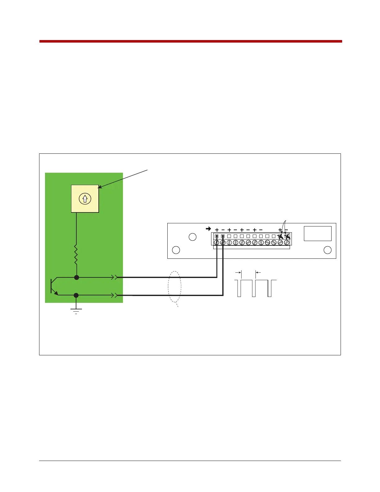
Figure 42. Wiring Pulse Output To A TLS-350 Console
TLS-350 Console with BIR
Low Voltage DIM Module
Pulse Input
IB Circuit Board
DH1-POUT-A
Ground
<500 feet
12V
1.072 ms
0V
Pulse out waveform
from EMR4 IB
P1
LOW VOLTAGE DISPENSER INTERFACE MODULE
PULSER
P2 P3 P4 SOURCE
INPUT RATING
30 VDC MAX
Source voltage
not required for
application shown
Setup both the EMR4 and the TLS for the same ratio of pulses to volume.
Reference the appropriate setup and operating manuals.
EMR4 IB Pulse Output
Voltage Rotary Switch
(In this example set to 12VDC)
5VDC 24VDC
12VDC
0VDC
5VDC 24VDC
12VDC
0VDC
1
3
2
0

 Loading...


