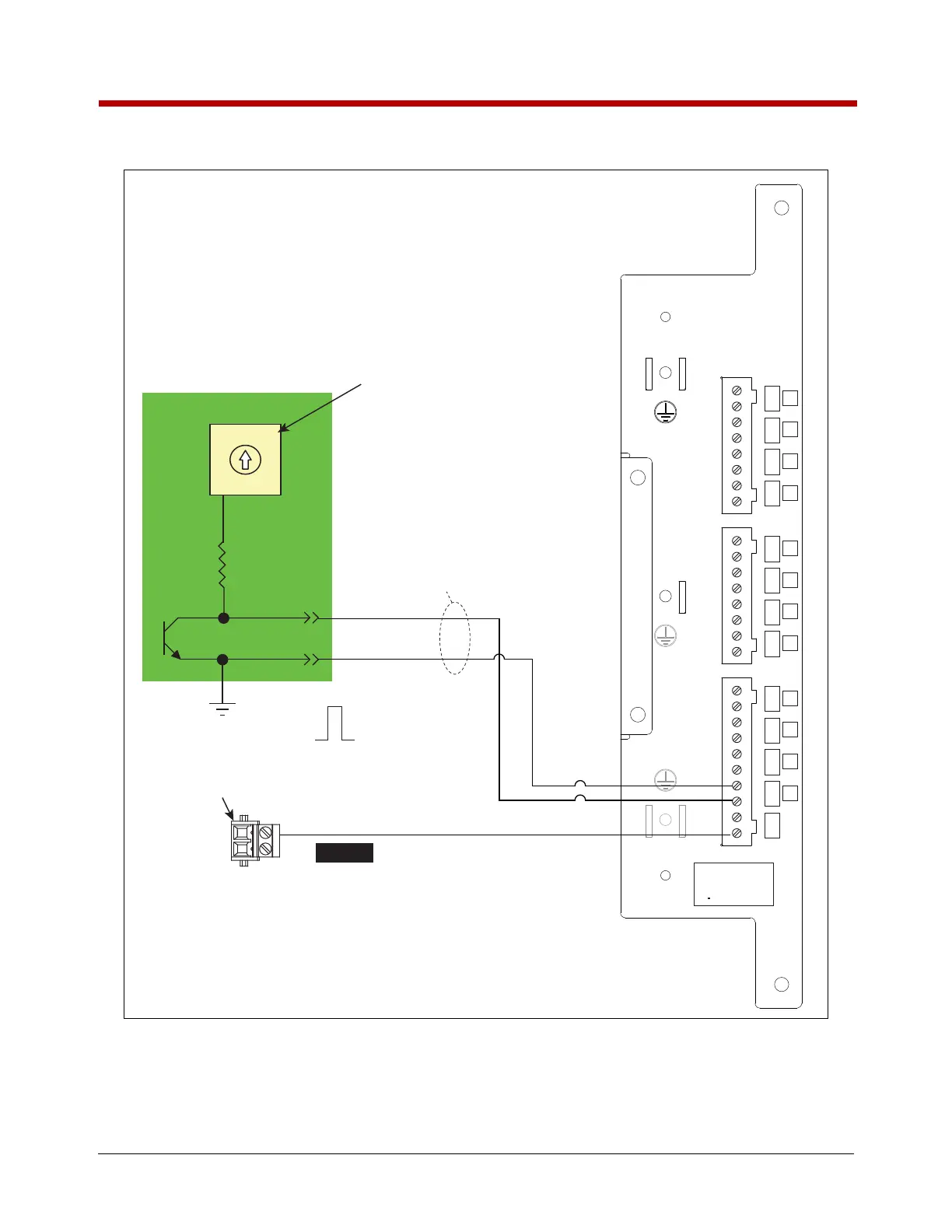
Figure 43. Wiring Pulse Output To A TLS-450/TLS4 Console
IB Circuit Board
IB Input Power
Connector (J8)
EMR4 IB Pulse Output
Voltage Rotary Switch
(In this example set to 12VDC)
5VDC 24VDC
12VDC
0VDC
5VDC 24VDC
12VDC
0VDC
1
3
2
0
Ground (-)
12V
0V
To external
pulse counter
Setup both the EMR4 and the TLS for the same ratio of pulses to volume.
Reference the appropriate setup and operating manuals.
LVDIM
LOW VOLTAGE DISPENSER INTERFACE MODULE
+
-
+
-
+
-
+
-
12
11
10
9
+
-
+
-
+
-
+
-
5
6
7
8
+
-
+
-
+
-
+
-
1
2
3
4
+
-
SOURCE
INPUT RATING
30 VDC MAX
0 1 AMP MAX
<500 feet
INPUT-PWR
GND
When supplying power from
EMR4 IB box, set switch SW1
on LVDIM PC board to the
“EXTERNAL” position.
DH1-POUT-A (+)
NOTICE

 Loading...


