EasyManuals Logo
Home>Veeder-Root>Measuring Instruments>EMR4

Veeder-Root EMR4 Application Guide

Veeder-Root EMR4
71 pages
To Next Page IconTo Next Page
To Previous Page IconTo Previous Page
Page #39 background imageLoading...
Page #39 background image
34
EMR
3
- Truck Installations
EMR4 Truck Installation 3-Way Safety Valve for Truck LP Gas Systems
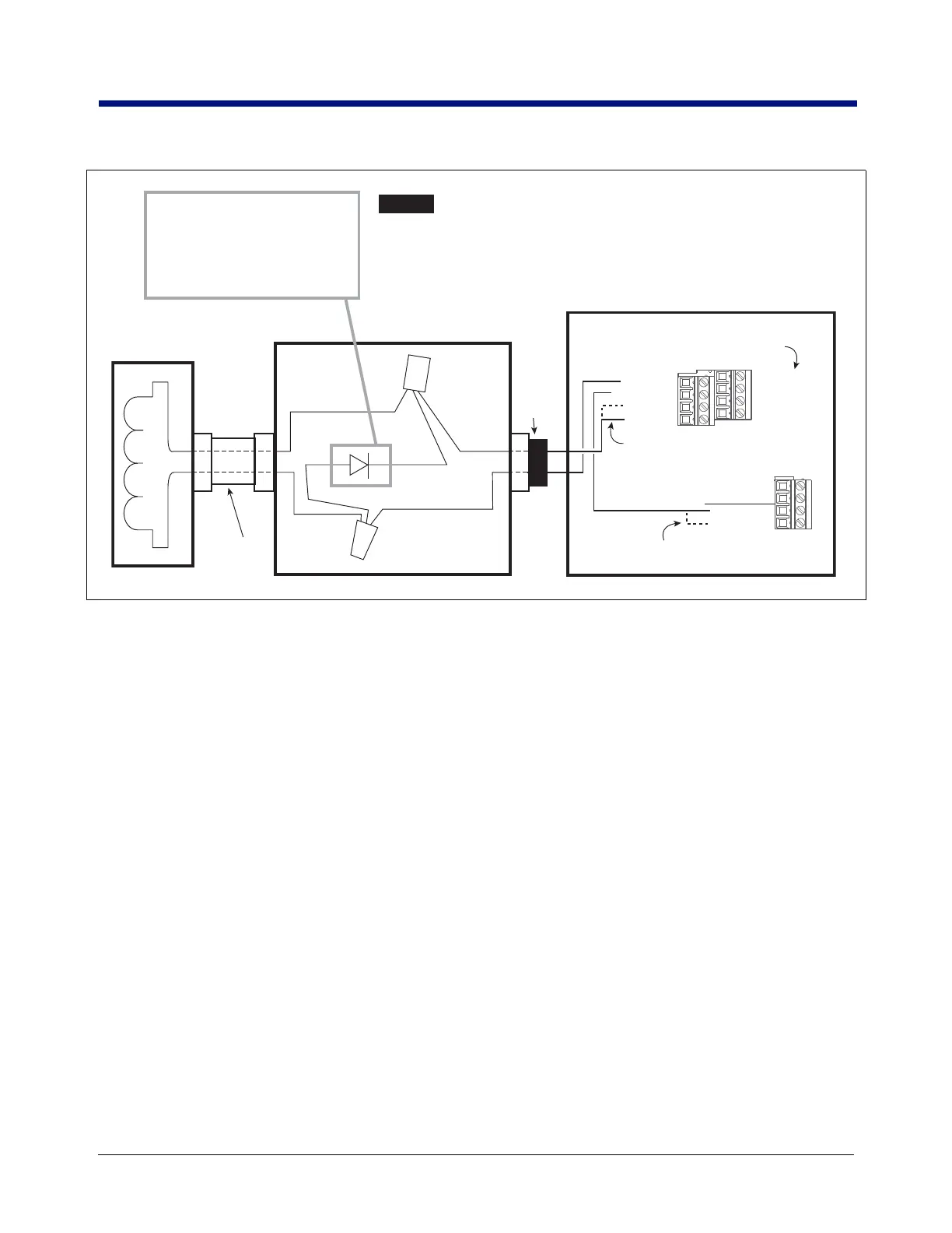
Figure 26. Connecting 3-Way Valve To The Interconnect Box
SOLENOID VALVES
Figure 27 illustrates wiring examples when connecting DC or AC solenoid valves to the IB box.
Wire nut
Red
Red
Black
Black
White
White
Wire nut
3-Way Valve
Solenoid
Cord
Grip
Nipple
J-Box
Suppression Diodes can only be
used with DC powered solenoids.
Suppressor diode
V/R Kit P/N 846000-022
Suppressor Diode Ratings:
Output Current of 1.0 Amp,
Maximum reverse voltage 420 Volts
Interconnect Box
Power-Side Terminals
J7
J8
DH1-R1-NO
DH1-R1-COM
INPUT-PWR
INPUT-PWR
DH2-R1-NO
DH2-R1-COM
INPUT-PWR
INPUT-PWR
INPUT-PWR
GND
CHASSIS-GND
CHASSIS-GND
Note: Use either INPUT-PWR terminal
to provide power to valve
Note: Use either CHASSIS-GND terminal
to provide return for valve
Note: Use DH2-R1-NO and DH2-R1-COM
if using Display Head 2 to control valve
NOTICE

Table of Contents

Other manuals for Veeder-Root EMR4

Questions and Answers:

Question and Answer IconNeed help?

Do you have a question about the Veeder-Root EMR4 and is the answer not in the manual?

Veeder-Root EMR4 Specifications

General IconGeneral
BrandVeeder-Root
ModelEMR4
CategoryMeasuring Instruments
LanguageEnglish

Related product manuals