22
EMR
3
- Truck Installations
EMR4 Truck Installation Neptune Flow Meter Installation
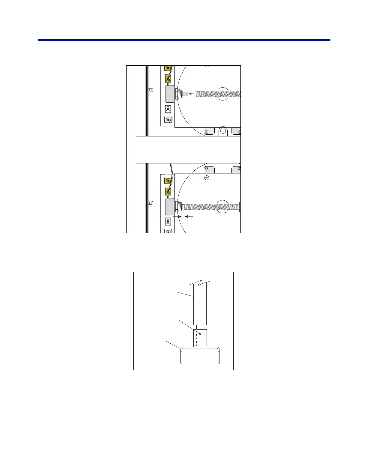
Figure 17. Pushing Encoder Spring Onto Pulse Encoder Shaft
16. With the end play within limits, get the coupling and groove pin from the kit and attach the coupling to the
bottom of the input shaft with the pin as shown in Figure 18.
Figure 18. Attaching Coupling To Neptune Adapter Shaft
17. Orient the encoder input shaft coupling so that it ‘mates’ with the meter adapter input shaft, then lower the
Display Head onto the meter adapter mounting flange.
18. Rotate the Display Head on the meter adapter mounting flange until the display is facing in the desired
direction and check to see that the four meter adapter flange mounting holes align with four of the eight
tapped (1/4 - 28 UNF-2B threads) mounting holes in the base of the Display Head’s housing. You may have to
Groove pin
from kit
4” Encoder
Input shaft
Coupling
from kit

 Loading...


