51
EMR
3
- Truck Installations
EMR4 Terminal & Fueling Depot Installation Installing the Interconnect Box
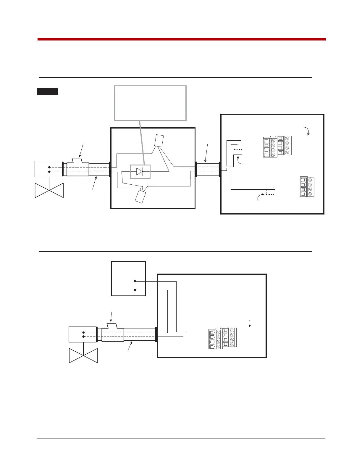
Figure 40. Example Wiring Connections For DC And AC Solenoid Valves
DC Solenoid
valve
Rigid conduit
Seal off
J-Box
Rigid
conduit
L
N
Supply
120/240 Vac
1
Interconnect Box
Power Side terminals
AC Solenoid
valve
Rigid conduit
Sealoff
AC Solenoid Wiring
DC Solenoid Wiring
Wire nut
Red
Red
Black
Black
White
White
Wire nut
Suppressor diode
V/R Kit P/N 846000-022
Suppressor Diode Ratings:
Output Current of 1.0 Amp,
Maximum reverse voltage 420 Volts
Suppression Diodes can only be
used with DC powered solenoids.
Interconnect Box
Power-Side Terminals
J7
J8
DH1-R1-NO
DH1-R1-COM
INPUT-PWR
INPUT-PWR
DH2-R1-NO
DH2-R1-COM
INPUT-PWR
INPUT-PWR
INPUT-PWR
GND
CHASSIS-GND
CHASSIS-GND
Note: Use either INPUT-PWR terminal
to provide power to valve
Note: Use either CHASSIS-GND terminal
to provide return for valve
Note: Use DH2-R1-NO and DH2-R1-COM
if using Display Head 2 to control valve
Note: Use DH2-R1-NO and DH2-R1-COM
if using Display Head 2 to control valve
J7
DH1-R1-NO
DH1-R1-COM
INPUT-PWR
INPUT-PWR
DH2-R1-NO
DH2-R1-COM
INPUT-PWR
INPUT-PWR
NOTICE

 Loading...


