Appendix A: EMR4 Safety Instructions & System Specifications EMR4 System Specifications
A-2
All ATEX models of the EMR4 DH are in compliance with Directive 2014/34/EU (ATEX).
A sample EMR4 DH has been evaluated and tested by UL International Demko A/S, Borupvang 5A, 2750
Ballerup, Denmark Tel.+45 44 85 65 65, info.dk@ul.com, www.ul.com and approved by the issue of the EC type
certificates:
DEMKO 17 ATEX 1889X or IECEx UL 17.0054X
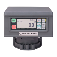
EMR4 Display Head
EMR4 Remote Pulser + Encoder
Symbol X used as suffix in all of the EC type test certificates listed above indicates the need for observing
special conditions for safe use. Further information is provided in each respective EC type certificate under the
paragraph, SPECIAL CONDITIONS FOR SAFE USE.
The manufacturers Quality System has been reviewed and is notified by SGS Baseefa, Staden Lane, Buxton,
Derbyshire SK17 9RZ, United Kingdom authorizing the use of its ID 1180 in conjunction with the CE mark. The
manufacturer is notified via SGS Baseefa QAN No. BASEEFA ATEX 1968. The CE mark may indicate compliance
with other relevant EC directives. Consult the manufacturers EC Declarations of Conformity for details.
In addition to certified intrinsically safe apparatus, Veeder-Root also provides simple apparatus that comply with
the requirements of EN 60079-11, Clause 5.7. These devices include; Thermoprobe, Emergency Stop Switch,
Corner Switch and the Optional Keypad. Figures showing these devices may contain devices that are outside the
scope of this ATEX Certificate.
EMR4 System Specifications
COMPONENT LOCATION
The EMR4 system should be located on a fuel delivery vehicle as shown in Figure 1 on page 5 or in a fueling
depot as shown in Figure 36 on page 44.
The equipment is designed to operate safely under the following range of conditions:
• Altitude up to 2000m.
• Temperature range - see Table A-1.
• A maximum relative humidity of 95% RH (non-condensing) at temperatures shown in Table A-1.
• A supply voltage fluctuation not exceeding 28 Vdc.
• Pollution Degree Category 2, Installation Category II.
• Vibration: MIL-STD-810G, Method 514.6; Table 514.6 C-VI Category 4
• Shock: MIL-STD-810G, Method 516.6; 20G, 11ms, 1/2-Sine
EMR4 IB units are not suitable for external locations and must be installed within the
interior of buildings or the cab of the fuel delivery vehicle.
Ensure that the
EMR4 IB is located where neither the unit itself nor its associated cabling will be damaged by
doors, furniture, barrows, etc. - depot installs or nearby equipment - vehicle installs.
Consider the ease of routing wiring, ducting and cables to the
EMR4 IB.
I Category 1: suitable for installation in Zone 0, Zone 1 or Zone 2 hazardous areas
G For potentially hazardous areas characterised by the presence of gases, vapours or mists
c1180
Equipment marking is compliant with requirements in the CE Marking Directive.

 Loading...


