B-3
Appendix B: Installing/Replacing Pulse Encoder Kit
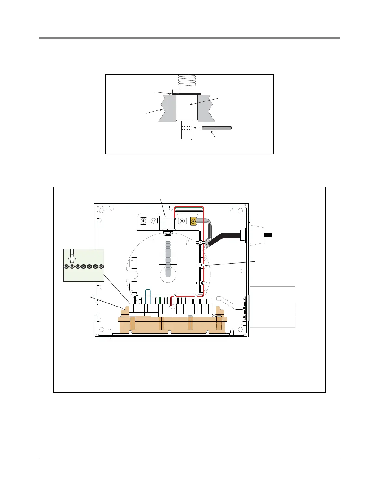
Figure B-4. Securing Encoder Input Shaft In EMR4 Base
7. Connect pulse encoder wires to display assembly terminal block as shown in Figure B-5.
Figure B-5. Connecting Pulse Encoder Wiring To Display Assembly Terminal Block
play Head Base
0.005" (0.127 mm)
washer from kit
Encoder input shaft
Groove pin
P/N 510162-001
ENS1J-489ENS1J-489
-L00100 -L00100
BOURNS BOURNS
VR ENCODERVR ENCODER
P/N P/N
331884-001331884-001
331933-001331933-001
I.S.I.S.
Route cables as shown to
avoid interference with flexible
encoder shaft. Use tie wraps
to attache cables to base.
Pulse encoder
Optional keypad
Display head
terminal block
9/64” (3.5mm) max.
Note: Maximum screwdriver
size for attaching wires to
terminal block.
GRN
IB-A
INTERCONNECT BOX
1000 RPM ENCODER OPTIONAL KEYPADTEMP PRBINTERLOCK
STOP SWC & C SW
BLK
GND
WHT
IB-B
RED
PWR
YEL
+
YEL
GND
WHT
+
BLK
GND
GRN
CHA
WHT
CHB
BLK
GND
RED
+5V
WHT
+
BLK
GND
WHT
+
BLK
GND
ORA
KP8
BLU
KP7
YEL
KP6
GRN
KP5
WHT
KP4
BLK
KP3
RED
KP2
NOT
USED
Wire Color
Red
Black
White
Green
Terminal
+5V
GND
CHB
CHA
Pulse Encoder Cable Connections

 Loading...


