Note: To retain these settings over the next power cycle or reset, click the Save Configuration button.
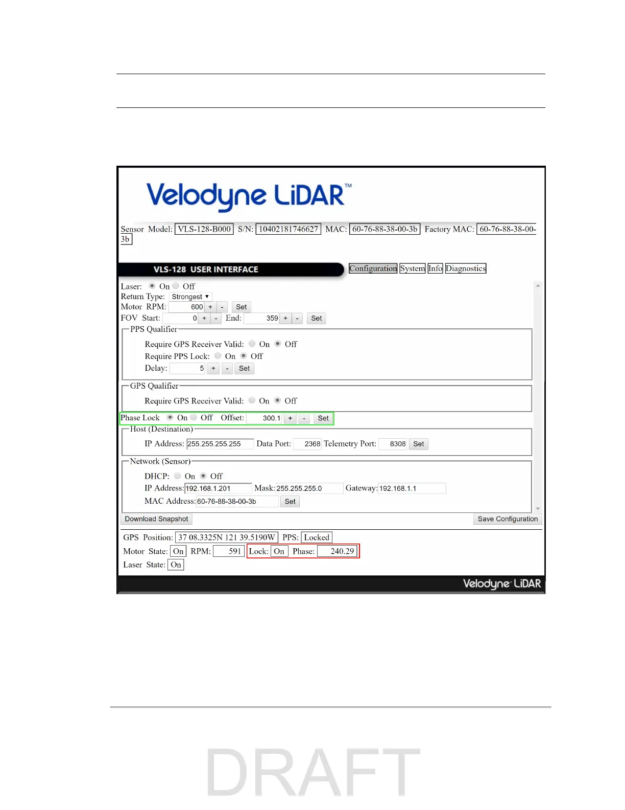
The current phase lock status (On/Off) and phase lock offset can be viewed on the Web Interface (red box). The current
phase lock offset is presented in degrees. The accuracy of the offset is ±5° (subject to change).
Figure H-2 Configuration Screen - Phase Lock
H.1.2 Application Scenarios
When setting the phase lock offset for two or more sensors, Velodyne recommends the sensors be configured to fire at
each other. This is the optimal configuration for minimizing interference because the location of the interference is under
user control.
Appendix H • Phase Lock 121

 Loading...


