Chapter 4 • Unboxing & Verification
This chapter provides the procedure to test and verify that your sensor is operating properly. Do this to check out a new
sensor before permanently mounting it somewhere.
4.1 What’s in the Box?
22
4.1.1 Bulkhead Connectors
22
4.1.2 Accessories
22
4.1.3 Variants
23
4.2 Verification Procedure
23
4.2.1 Network Setup in Isolation
23
4.2.2 Access Sensor’s Web Interface
25
4.2.3 Visualize Live Sensor Data with VeloView
26
4.1 What’s in the Box?
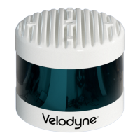
A standard Velodyne VLS-128 sensor comes packaged in its own cardboard box.
Ensure all the components are present:
VLS-128 sensor in a protective shroud.
Velodyne USB memory stick, containing:
User Manual
VeloView application installers for PC, Mac, and linux
Sensor sample data (i.e. pcap files)
Miscellaneous documents
4.1.1 Bulkhead Connectors
The VLS-128 has two bulkhead connectors on the bottom of the sensor, enabling cabling to be hidden from public view
while shielding them and the connectors from the elements. Placement of the connectors can be found in the
VLS-128
Mechanical Drawing on page 101
.
4.1.1.1 Ethernet Bulkhead Connector
Molex P/N 120341-0150 (datasheet)
4.1.1.2 Power+GPS Bulkhead Connector
Molex P/N 120244-0022 (datasheet)
4.1.2 Accessories
Interface boxes from other sensor types (e.g. VLP-32C) are not compatible with VLS-128 sensors. They are not inter-
changeable. In particular, note the different ratings for the fuses.
22 VLS-128 User Manual

 Loading...