RPM Resolution
300 0.09594°
600 0.19188°
900 0.28782°
1200 0.38376°
Table 8-1 Rotation Speed vs Resolution
8.3.2 Rotation Speed Fluctuation and Point Density
Your sensor uses a feedback control function to maintain its rotational speed within ±3 RPM of its configured setting. This
small variation in speed produces a small change in the azimuthal gaps with every revolution. Consequently, over time, the
sensor automatically “fills in the gaps” between successive laser firings.
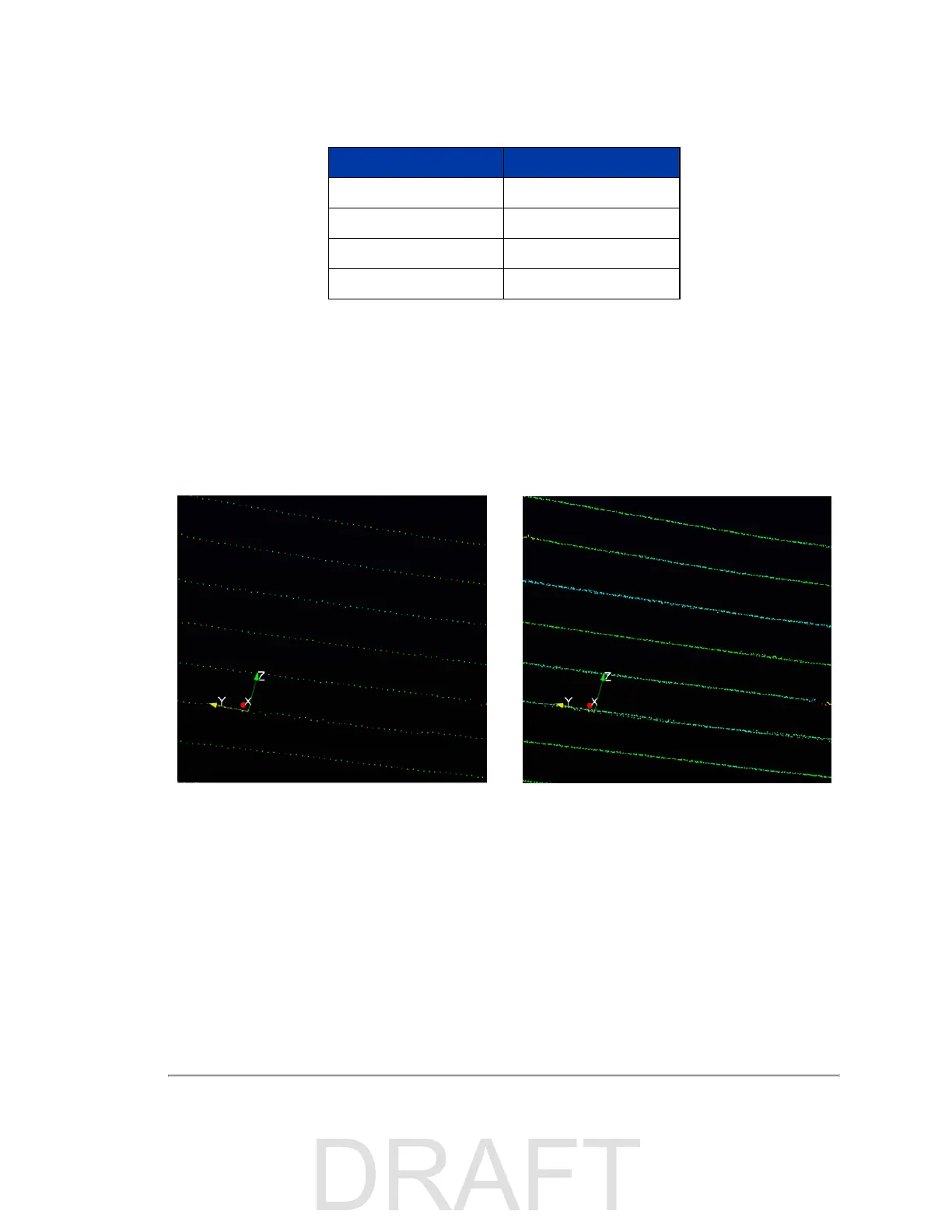
A data set from a stationary sensor provides an example of the how the sensor “fills in the gaps,” and the effect is demon-
strated in
Figure 8-1 below
. On the left is a single frame of data. On the right is the same frame and the nine preceding
frames overlaid on each other. You can see how the azimuth gaps are filled.
Figure 8-1 Point Density Example
Chapter 8 • Sensor Operation 51

 Loading...


