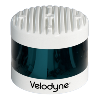
Optional components include:
2 m Gigabit Ethernet cable: CAT6A, Molex-to-RJ45, IP67, 8 conductor, 26 AWG, braided shielding
10 m Gigabit Ethernet cable: CAT6A, Molex-to-RJ45, IP67, 8 conductor, 26 AWG, braided shielding
2 m GPS+Power cable, Molex-to-Molex, 8 conductor (4 power, 4 signal), braided shielding, 22 AWG power, 26
AWG GPS
10 m GPS+Power cable, Molex-to-Molex, 8 conductor (4 power, 4 signal), braided shielding, 22 AWG power, 26
AWG GPS
Interface Box with 7.5 A fuse and 3 m hardwired Molex power cable
Standalone Interface Box with 7.5 A fuse and mating Molex connector
Each Interface box includes a 1.8 m AC power adapter.
Accessories are available for purchase either directly from Velodyne Sales or from a reseller.
4.1.3 Variants
Variants of the sensor exist, particularly with other connector types and/or cable lengths. Your sensor (or the type you are
interested in) may vary from the standard configuration above. Contact Velodyne Sales for details.
4.2 Verification Procedure
The purpose of this procedure is to verify the sensor’s basic functionality and get you started on your way to processing
sensor data in (or from) the field. It involves one computer and one sensor in isolation at a workbench or desk. You’ll need
AC power. You won’t need a GPS receiver.
Note: Due to the large volume of data produced by the sensor when scanning, users are cautioned against connecting it
to a corporate network.
1. Unpack the sensor and its accessories, and place them on a workbench or desk. Ensure the sensor is upright with
clear space around it.
2. Create a simple network setup with a test computer and the sensor in isolation. Follow the procedure in
Network
Setup in Isolation below
.
3. Use the sensor’s Web Interface to perform basic sensor configuration. Follow the procedure in
Access Sensor’s
Web Interface on page 25
.
4. Use VeloView (or other visualization software of your choice) to view data streaming from your sensor. Follow the
procedure in
Visualize Live Sensor Data with VeloView on page 26
.
When finished, the sensor should be ready for more complicated usage scenarios.
4.2.1 Network Setup in Isolation
Your sensor’s IP address comes from the factory set to its default value, 192.168.1.201. This procedure prepares a com-
puter to communicate directly with the sensor at that address.
Note: If using the computer’s main Ethernet port, disconnect it from whatever network it’s on. If using a secondary Eth-
ernet interface, the primary network cannot be a 192.168.1 network. If it is, use the primary Ethernet interface instead.
Chapter 4 • Unboxing & Verification 23

 Loading...