7.2 Interface Box Signals
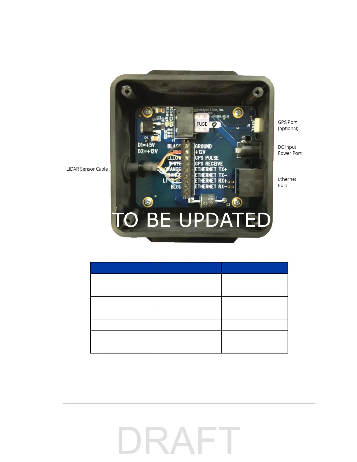
Figure 7-1 Interface Box (sensor power and data connections)
Signal Specifications Signal Input/Output
Black Ground Input
Yellow GPS Sync Pulse Input
White GPS Serial Receive Input
Light Orange Ethernet TX+ Output
Orange Ethernet TX- Output
Light Blue Ethernet RX+ Input
Blue Ethernet RX- Input
Table 7-1 Interface Box Signals
Chapter 7 • Sensor Inputs 39

 Loading...


