}
},
}
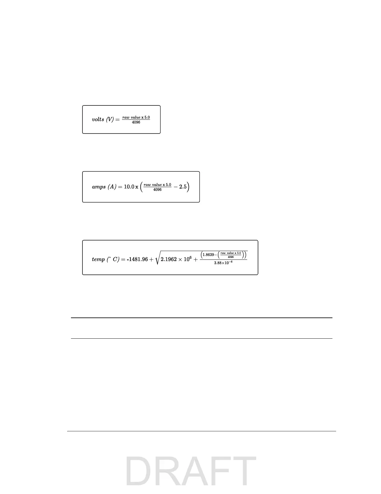
10.2.3.2 Conversion Formulas
Equation 10-1 Standard Voltage Conversion
Equation 10-2 Standard Current Conversion
Equation 10-3 Standard Temperature Conversion
10.2.3.3 Interpret Diagnostic Data
Use the formulas above to convert raw diagnostic data fields below to usable values. Some fields are scaled by additional
factors.
Note: Operating range values in this section are subject to change.
10.2.3.3.1 top:hv
The HV field comes from the sensor's top board. It represents the high voltage bias to the APD (Avalanche photodiode).
Its operating range is -150.0 V to -132.0 V.
To convert the raw value, use
Equation 10-1 above
then scale the result by subtracting 5.0 and multiplying the result by
101.0.
Chapter 10 • Sensor Communication 77

 Loading...


