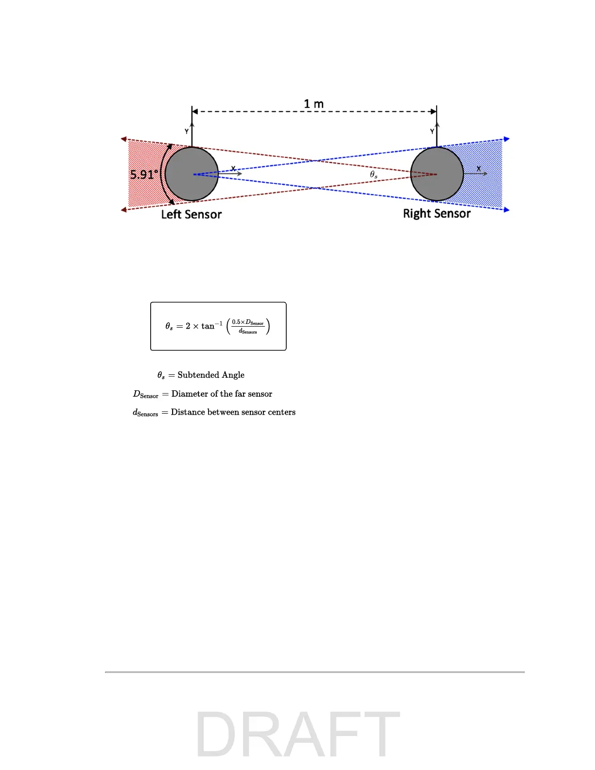
Figure H-5 Sensor Data Shadows
The angle subtended by the shadow of a sensor in range but at some distance from another sensor is given by the fol-
lowing formula:
Equation H-1 Arc of Shadow
Data reported at the azimuths included within the subtended angle should be ignored.
H.2 Field of View
Alternatively, each sensor's Field of View control may be used to remove the subtended azimuths from the data stream.
Use
Figure H-5 above
and
Equation H-1 above
to determine for each sensor the azimuthal angles at which the shadows
begin and end.
Then, using each sensor's Web Interface or curl commands (or equivalent programmatic commands), configure the
sensor's horizontal FOV start and end angles. See
Configuration Screen on page 68
and
Set Field of View on page 82
for
more.
H.3 Status
No version of VLS-128 firmware has been released yet. Below are notes on pre-release revs regarding Phase Lock.
Release 5.0.5.x of the firmware has a bug related to PPS and Phase Lock. Phase Lock may be enabled and PPS locked,
but the phase achieved will differ from the phase offset you set by roughly 60 degrees.
Appendix H • Phase Lock 123

 Loading...


