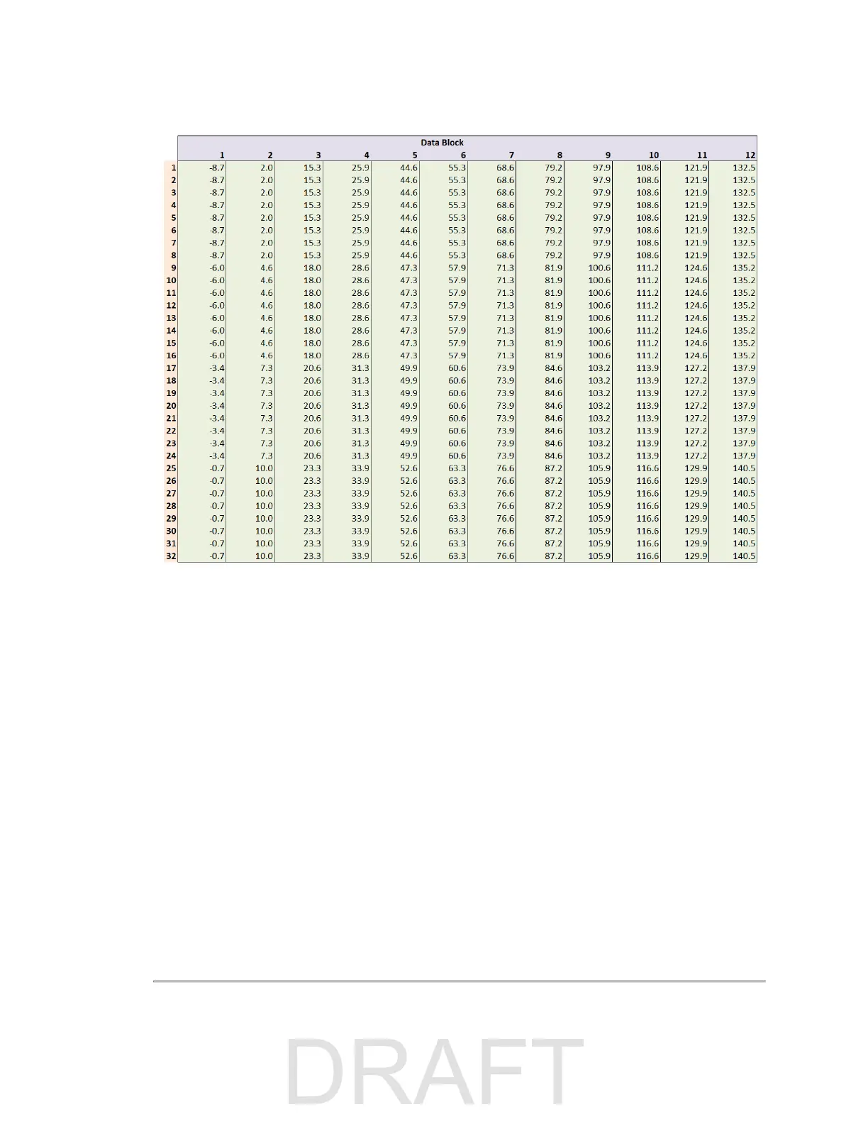
Figure 9-6 Single Return Mode Timing Offsets (in µs)
Figure 9-7 Dual Return Mode Timing Offsets (in µs)
TBD
9.5 Precision Azimuth Calculation
The azimuth (α) in each data block represents the center line of the firing pattern at the moment the first firing group in a fir-
ing sequence occurred. But, because all of the lasers are offset from the center line by fixed amounts, an azimuthal offset
must be applied to determine the precise azimuth of each data point. The figures below provide both the angular offsets to
apply per laser, and an illustration of where the offsets put the laser in the firing pattern.
62 VLS-128 User Manual

 Loading...


