Signal Timing Plans We value your opinion
Ver-Mac 2018 V-Touch TLD User's Manual – V3.2 18
3. Continue adding phase diagrams until the signal plan (cycle) is complete. Then
you can proceed to set the green interval times for each phase.
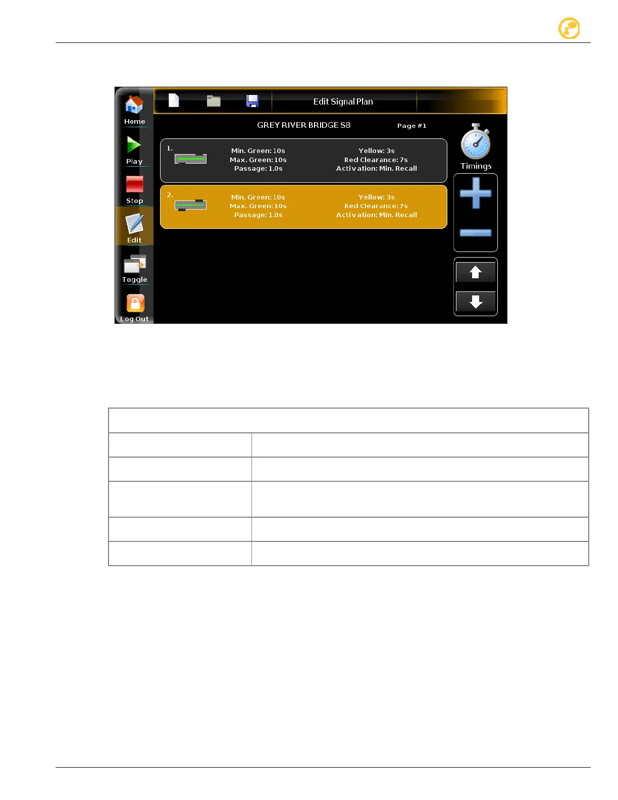
Figure 13: Edit Signal Plan screen with cycle complete (all phases)
5.3.4 Step 4: Set the Green Interval Timings
To regulate each phase of the signal plan (cycle), you have to define the green interval
times for each phase.
The shortest amount of time the signal displays green for a particular
traffic movement.
The maximum amount of time the signal can display green after any
call for an opposing phase.
The amount of time by which the minimum green time is increased for
each detector actuation by a vehicle. The green time extends until the
You can change yellow timing previously set (see Figure 10) for that
specific signal head.
You can change red timing previously set (see Figure 10) for that
specific signal head.
Table 3 - Green interval times
1. In the Edit Signal Plan screen (see Figure 13), tap to select the first phase
diagram of your sequence (cycle).
2. Tap Edit in the Phase Editor screen.