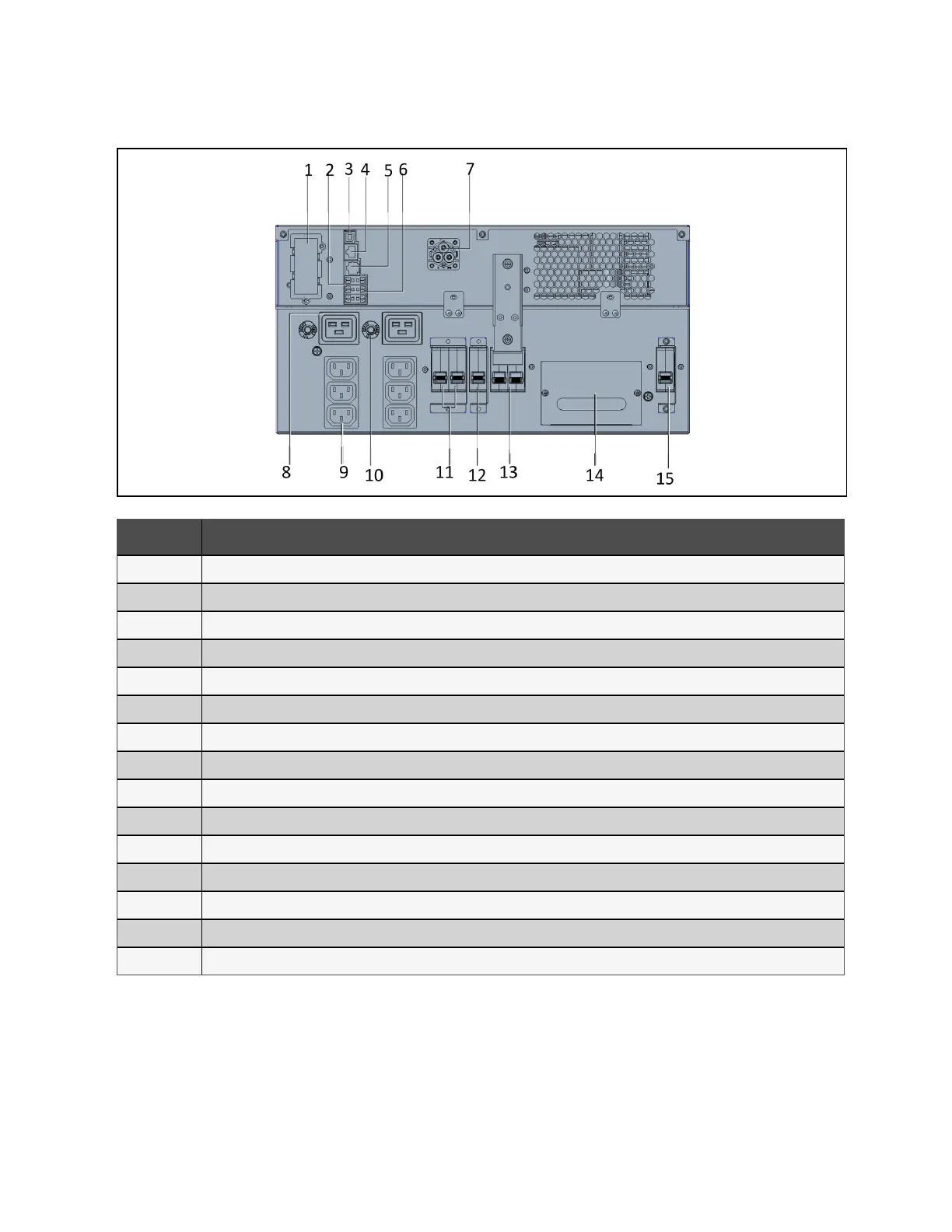
Figure 2.10 GXT5-5000/6000IRT5UXLN (XLE) Rear Panel
Item Description
1 Vertiv™ Liebert® IntelliSlot™ port
2 Terminal-block communication connectors
3 USB port
4 RS-485 port - RJ-45 connection used for external temperature sensors
5 RS-232 port - RJ-45/RJ-11 connection used for command line interface
6 REPO connector
7 EBC connector
8 C19 output receptacles (x2)
9 Programmable C13 output receptacles (x2)
10 C19 output overload protector (x2)
11 Programmable output circuit breaker, 10 A (x2)
12 Output circuit breaker - Controls terminal block output and non-programmable output receptacles
13 Maintenance bypass breaker (MBB)
14 Removable junction box with cable entry for hard-wire I/O
15 Input circuit breaker
2 Product Description Proprietary and Confidential ©2024 Vertiv Group Corp. 13
Vertiv™ Liebert® GXT5 UPS Installer/User Guide