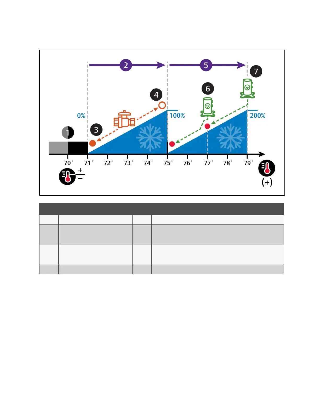
Figure 7.1 Temperature Control—Fluid Economizer and Example Two Step Compressor Capacity
No. Description No. Description
1 Deadband. 5 ½ of proportional band assigned tocompressor(s) operation.
2
½ of proportional band assigned
tovalveoperation.
6
Scroll compressor step 1.
(Compressor 1 in dual compressor configuration, Unloaded in single compressor
configuration.)
3 Fluid control valve closed. 7
Scroll compressor step 2.
(Compressor 2 in dual compressor configuration, Loaded in single compressor
configuration.)
7 Fluid control valve fully open.
7 Configuring Economizer Operation
114
Vertiv™ Liebert® iCOM™Installer/User Guide