2. Terminate the ground wire to a field installed ground ring in the low voltage electrical panel, as shown in Figure
13.11 below .
3. Connect the CANbus cable to the cooling unit.
On most cooling units, the connection points for the CANbus link are P66 and P67.
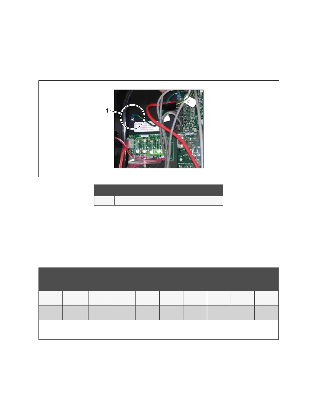
Figure 13.11 Ground Wire Ring Connection
Item Description
1 CANbus cable grounding ring connected to grounding screw in unit.
13.3 Installing a Fluid Temperature Sensor
1. Locate the DIP switches in the 2T sensor(s) by removing rear housing or via pre-cut hole in housing, Figure 13.12
on the next page , and program according to Table 13.4 below .
Figure 13.13 on the next page , shows the switch and on/off setting.
CANbus
Node ID
DIP Switch Position
1 2 3 4 5 6 7 8
Fluid
circuit1
30 Off On On On On Off Off Off
Fluid
circuit2
31 On On On On On Off Off Off
Circuit 1 and 2 fluid sensors are dual-purpose CANbus IDs in firmware. These sensors might also be used for monitoring supply temperature. Before
installing fluid temperature sensors, determine whether or not the supply-temperature 2T sensors are in use. Adding duplicate sensors will cause sensor
communication loss.
Table 13.4 DIP Switch Settings in 2T Sensors
13 Vertiv™ Liebert® iCOM™ Hardware Installation
193
Vertiv™ Liebert® iCOM™Installer/User Guide