13.4.2 Installing Aggregated Supply Air Temperature Sensors
On systems with large supply air plenums, up to five additional 2T sensors may be connected (via CANbus) in addition to the
standard supply air sensor. Vertiv™ Liebert® iCOM™ then aggregates the readings and converts to average or maximum
values for supply control.
NOTE: The 2T sensors used for supply air sensor aggregation are identical to the wired remote sensors and are added
in addition to the up to 10 remote sensors. You may install the supply air sensors at the end of the wired remote
CANbus link or as a separate CANbus loop tied-back to the control board and properly terminated.
The sensor array consists of 2T sensors that each have two temperature probes on a 6 ft. (1.8 m) probe connection cable and
requires several steps to prepare, connect, and begin monitoring the racks:
• Set DIP switches in each sensor.
• Terminate final sensor on CANbus link.
• Install sensors.
• Install CANbus cabling between sensors.
• Connect CANbus cable to the cooling unit.
• Configure the sensors in Liebert® iCOM™.
13.5 Installing Analog Input Devices
External sensors and analog devices may be connected to Vertiv™ Liebert® iCOM™ using an electrical connection on the
iCOM™ control board to a required, factory-supplied plug, harness and terminal strip. (Contact Vertiv™ technical support for
parts.)
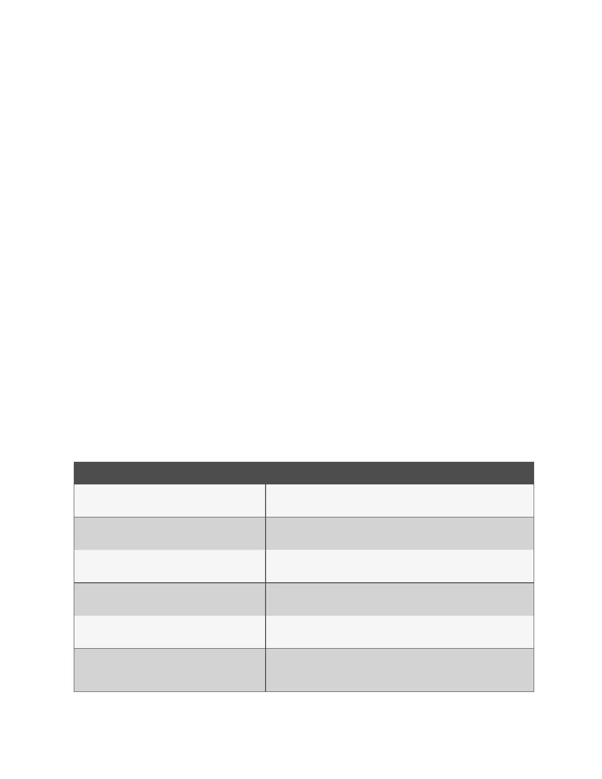
When equipped, devices as follows can be connected to terminals 41, 42, 43 and 44, 45 and 46, or 47 and 48. Table 13.5
below , lists available analog inputs depending on the type of cooling unit.
See Configuring Analog Input Devices on page157 , to configure the Liebert® iCOM™ settings for the device.
Cooling Unit Inputs Available
Liebert® CW and Liebert® PCW with MBV
4
2 may be used for valve feedback on CW, 1 on Liebert® PCW.
Liebert® CW and Liebert® PCW with3P(floating
pointactuator)
4
2 may be used for valve feedback on CW, 1 on Liebert® PCW.
Liebert® DS and Liebert® DSE Air-cooled
2
Both used for low pressure transducers.
Liebert® DS Water/Glycol Cooling
0
Models without high pressure transducers may have 2.
Liebert® PDX Air Cooled
3
1 is used for low pressure transducers.
Liebert® PDX Water/Glycol Cooled
2
1 is used for a low pressure transducer. Optionally, a second for a high pressure
transducer.
Table 13.5 Number of Analog Inputs Available by Cooling Unit Type
13 Vertiv™ Liebert® iCOM™ Hardware Installation
196
Vertiv™ Liebert® iCOM™Installer/User Guide