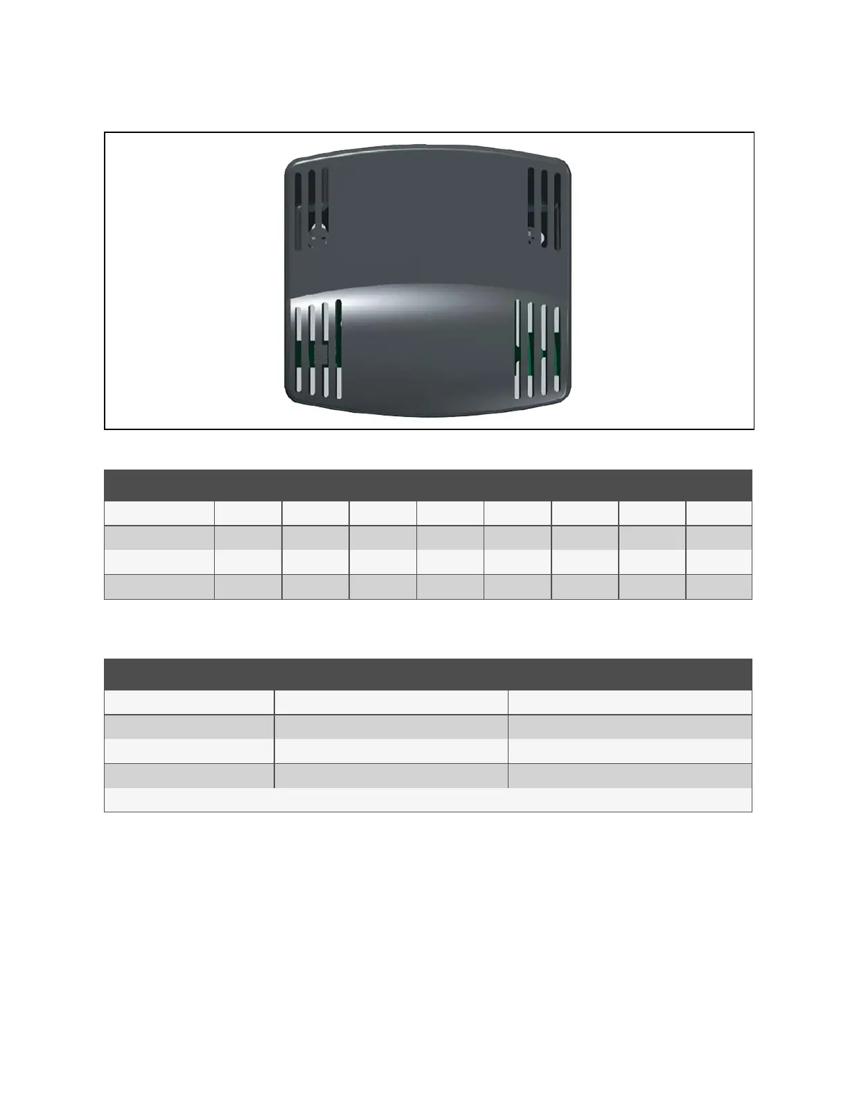
Figure 13.2 Optional Remote Sensor A, B, C
Sensor Pos. #1 Pos. #2 Pos. #3 Pos. #4 Pos. #5 Pos. #6 Pos. #7 Pos. #8
Return T/H Sensor Off Off Off Off Off Off Off Off
Optional Sensor A On Off Off Off On Off Off Off
Optional Sensor B Off On Off Off On Off Off Off
Optional Sensor C On On Off Off On Off Off Off
Table 13.1 Temperature/Humidity Sensor Dip Switch Settings
Jumper Label Type Position
P2 BDM Header *Open
P3 CANbus Termination *Shunt on Pins 2 and 3
P4 Programming *Open
E10-E13 Serial Port *Open
*Factory default positions and settings.
Table 13.2 Temperature/Humidity Sensor Jumper Settings
13.1.2 Jumper P3 CANbus Termination
The correct position of this jumper is dependent on your system configuration. If the sensor is physically the first or last node
in the CANbus device loop, the jumper must be terminated or shunted across pins #2 and #3 (default position). If the sensor is
a middle node in the CANbus device loop, the jumper must be unterminated or shunted across pins #1 and #2.
13 Vertiv™ Liebert® iCOM™ Hardware Installation
183
Vertiv™ Liebert® iCOM™Installer/User Guide