13.2.3 Installing 2T Sensors in the Racks to Monitor
Tools required:
• Medium, flat head screw driver to open electric panel dead front
• Cutting tool to trim cable ties
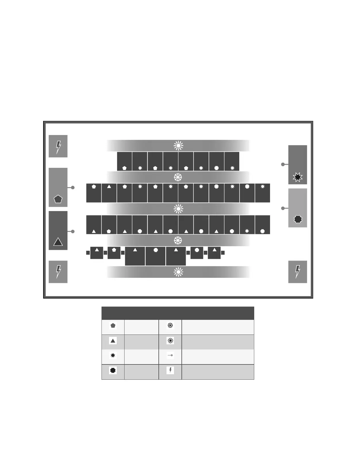
The cooling units and rack sensors in Figure 13.8 below are symbol coded to show how interlacing sensors from different
cooling units provides redundancy and effective operation by sharing sensor data from the cooling units in Teamwork mode.
Figure 13.8 Interlacing Sensor Placement
item Description Item Description
Unit 1 Cold aisle (frontofracks)
Unit 2 Hot aisle (rearofracks)
Unit 3 Supply(discharge) temperaturesensor
Unit 4 Power distribution unit
13 Vertiv™ Liebert® iCOM™ Hardware Installation
189
Vertiv™ Liebert® iCOM™Installer/User Guide