13.4 Installing Supply Control Sensors
13.4.1 Installing the Supply Air Temperature Sensor
The supply temperature sensor is connected to P8, Pins 1 and 2 at the factory and requires no configuration.
1. Place the sensor in an area that is influenced only by the unit to which it is connected to provide an accurate
reading: 5ft. to 15ft. (1.5m to 4.5m) from the cooling unit, Figure 13.14 below .
NOTE: A 50 ft. (15 m) extension cable is available from Vertiv™ if the sensor must be more than 15ft.(4.5m) from the
Vertiv™ Liebert® iCOM™ unit.
2. Confirm connectivity via SENSOR DATA. See Viewing Sensor Data on page20 .
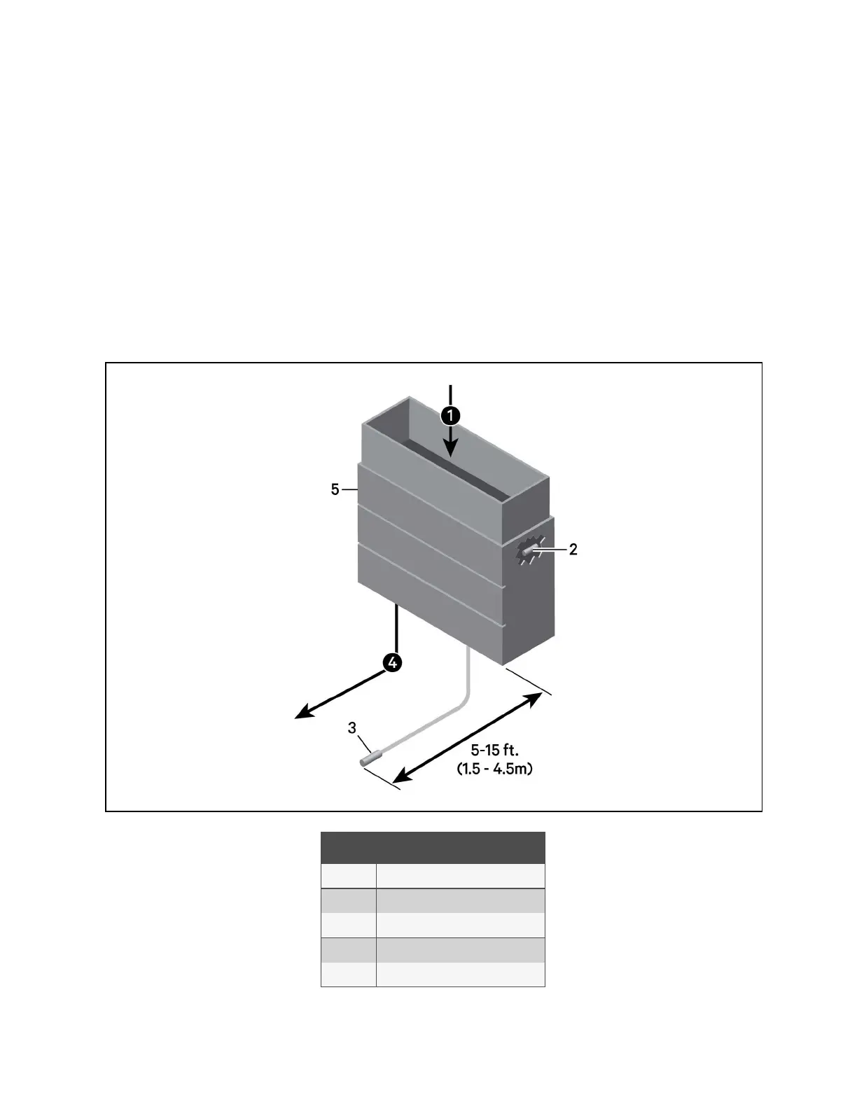
Figure 13.14 Placement of the Supply Air Temperature Sensor
Item Description
1 Return air
2 Internal temperature/humidity sensor
3 Temperature sensor
4 Supply air
5 Liebert® Thermal Management unit
13 Vertiv™ Liebert® iCOM™ Hardware Installation
195
Vertiv™ Liebert® iCOM™Installer/User Guide