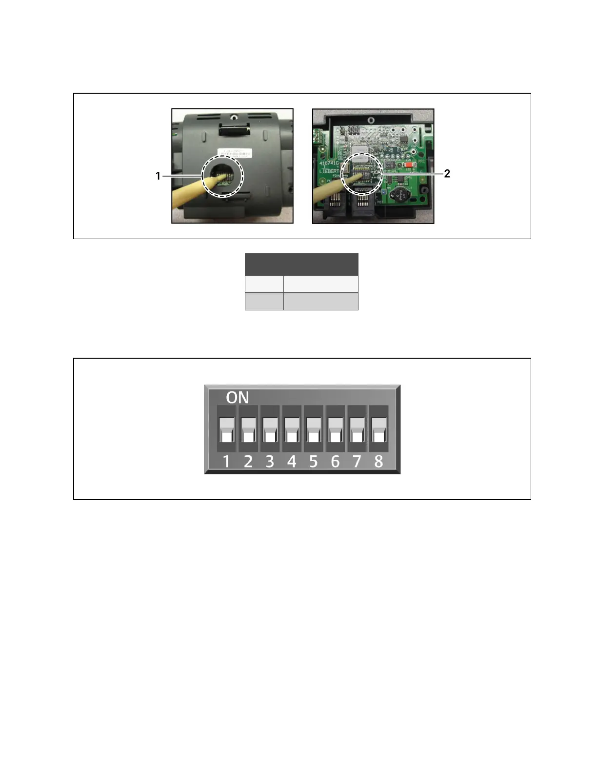
Figure 13.12 Locating DIP Switches in 2T Sensor
Item Description
1 Hole in sensor housing
2 Cover removed
NOTE: Up is on, down is off on the DIP switch.
Figure 13.13 DIP Switches in 2T Sensor
2. Once DIP switches are set, refer to Terminating the Last Sensor on the CANbus link on page186 , then continue
with step 3 .
3. On Vertiv™ Liebert® iCOM™:
• In the Service menu, touch Auxiliary Device Setup > Sensors > Fluid Sensors > Fluid 2T SensorCW T. The
SENSOR PROPERTIES panel opens.
• In Fluid Sensor Type, select the type of 2T sensor.
4. At the fluid inlet and outlet, use a field supplied temperature sensor to verify the temperature readings, compare
the Liebert® iCOM™ readings to the actual measured temperatures, and calibrate as needed.
• If inlet and outlet temperature readings in Liebert® iCOM™ are reversed based on the field measurements,
use Fluid Sensor 1/2 Placement to swap the readings.
5. Touch Save. The fluid temperature sensor settings are saved.
13 Vertiv™ Liebert® iCOM™ Hardware Installation
194
Vertiv™ Liebert® iCOM™Installer/User Guide