To connect the cables:
1. Connect CANbus cable and a ground wire between each sensor for the cooling unit, Figure 13.10 below , taking
the following precautions:
NOTE: Remember that the last sensor on the chain must be terminated as described in Terminating the Last Sensor on
the CANbus link on page186 .
• Use only approved hangers, and do not secure cables in a way that could damage them.
• Limit bends to less than four times the diameter of the cable.
• When securing and hanging, avoid deforming the cable.
• Keep cables away from devices that may cause interference such as high voltage wires, machinery,
fluorescent lights and electronics.
NOTE: High voltage sources much be at least 12 in. (305mm) from CAN wires.
• Avoid stretching cables.
• Avoid using excess cable between sensors.
• Make sure that cables have the correct pin out. Mismatched pins at the RJ12 connection will damage the
CAN device.
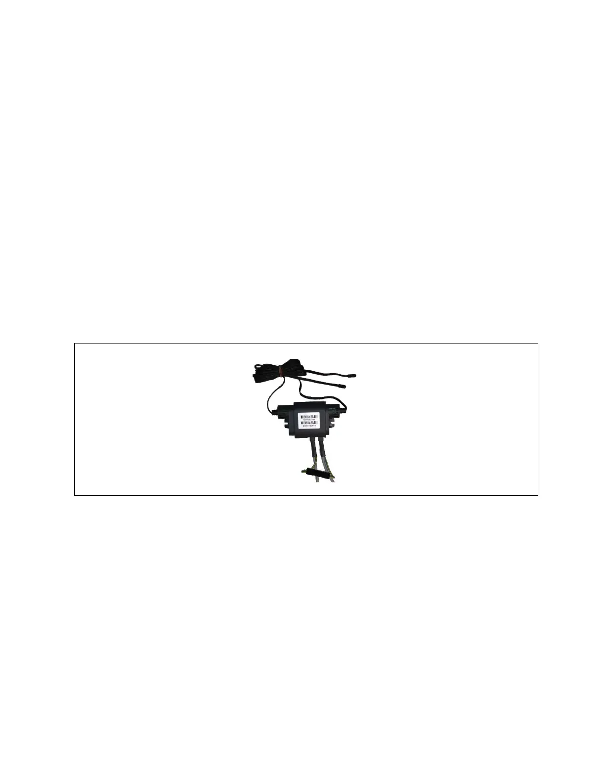
Figure 13.10 CANbus and Ground Connection on 2T Sensor
13 Vertiv™ Liebert® iCOM™ Hardware Installation
192
Vertiv™ Liebert® iCOM™Installer/User Guide