Vertiv | Liebert PEX+ Chilled Water | User Manual 25
Installation
Table 2-4 Dimensions of Air Outlet on Top Cover of Downflow Unit (inch/mm)
Types of Model
A B C
E
F G I
J
D H P
CI CO
mm mm mm mm mm mm mm mm mm mm mm mm mm
P1030~P1050 117 852 779
404 290 105 205 85 35 35 51x76 110 110
P1060 141 797 797
404 290 108 187 66 35 35 51x76 110 110
P2070-P2100 180 887 779
404 290 105 205 85 35 35 56 110 110
P2110-P2140 167 874 792
404 290 108 192 88 35 35 56 110 110
P3150 180 887 779
404 290 105 205 85 35 35 56 110 110
P3160 182 887 779
404 290 105 205 85 35 35 56 110 110
P3170-P3200 167 874 792
404 290 108 192 88 35 35 56 110 110
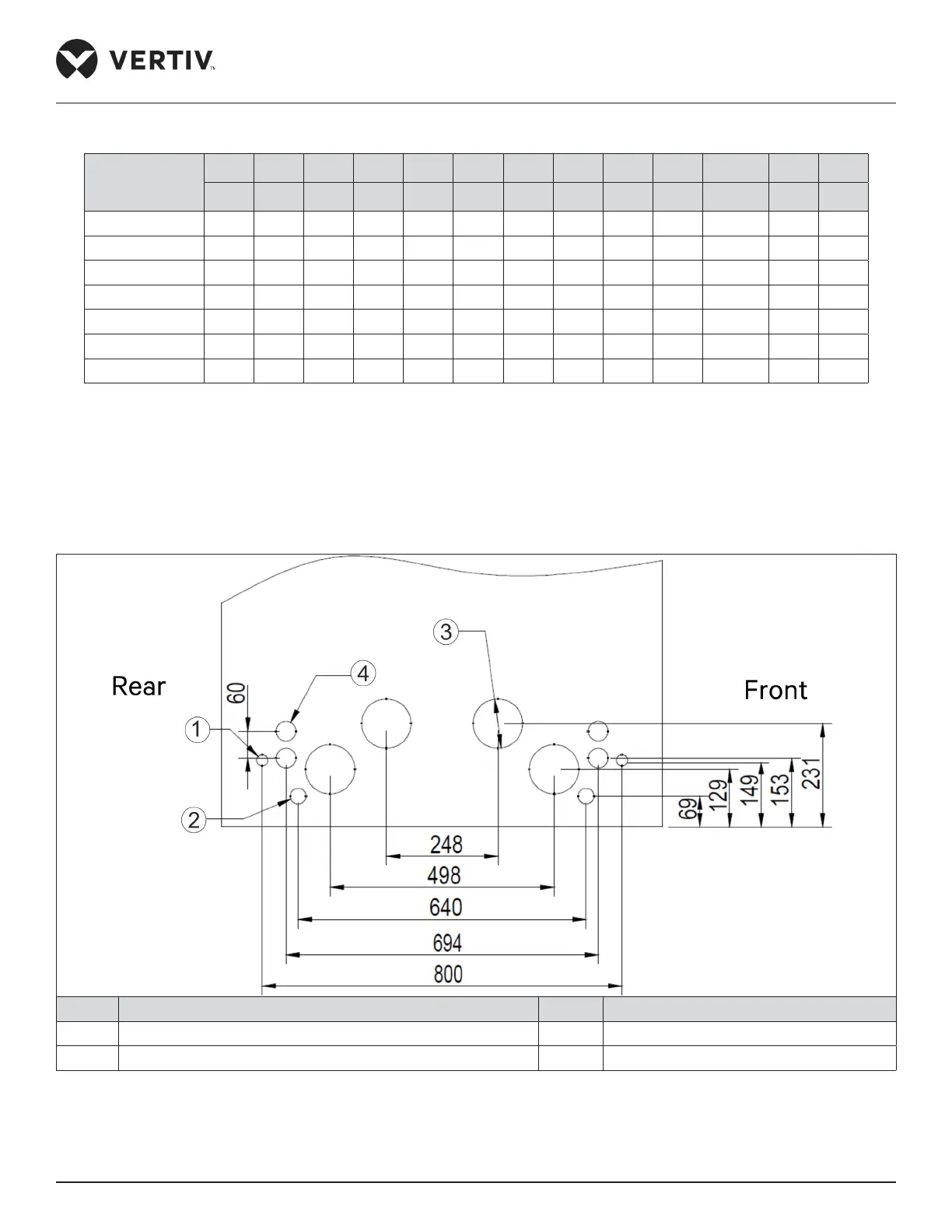
2.4.2. Side Panel Knock-out Location
If it is diicult to route piping and cabling from the base then route the connection from side panel. The locations
and dimensions of knock-out holes are shown in Figure 2-13 and Figure 2-14. Select the inlet and outlet holes
according to the requirements. Ensure only one service is used per opening.
No. Description No. Description
1 2-Ø25 Knock-out hole 3 4-Ø110 Knock-out hole
2 2-Ø35 Knock-out hole 4 4-Ø44 Knock-out hole
Figure 2-13 Knock-out Holes on Side Panel of the Upflow Unit (unit: mm)