98ENGINECOMPONENTANDLOCATION
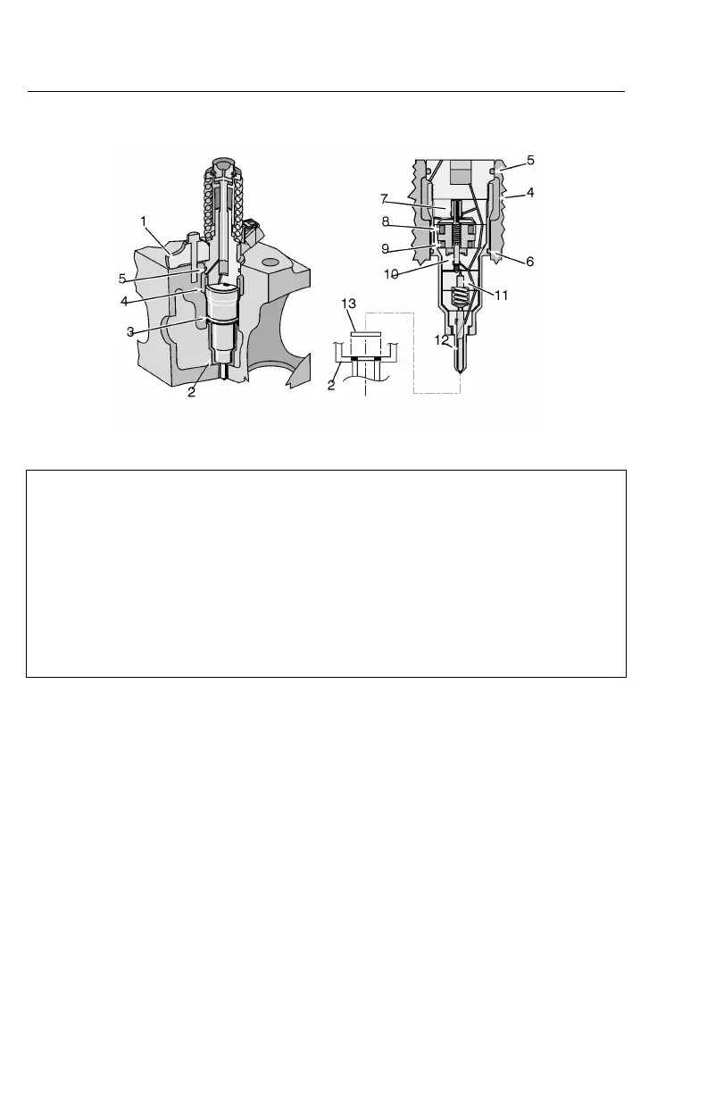
UnitInjectors
W2033328
1.InjectorYoke
8.SolenoidCoil
2.CopperSleeve9.SolenoidCoil
3.O-Ring
10.InjectorV alve
4.FuelGallery
11.InjectorPiston
5.O-Ring
12.InjectorNozzle
6.O-Ring13.Washer
7.PressureReliefV alve
Thisengineusesdoublesolenoidunitinjectors.Unlikesystemsthatrequireseparate
componentsfordelivering,pressurizingandinjecting,thisunitinjectorcombines
thesefunctions.Theseinjectorspreciselycontrolthefueldeliverybecauseofthetwo
solenoids.Thesolenoids,pumpandnozzleareinasinglebodyincloseproximity
toeachother.
Theinjectorissetinapressurizedfuelgallerywherethefueltemperatureisconstant.
Uniformfueltemperaturemeansuniformquantityineachinjectionwhichmeans
uniformpoweroutputfromeachcylinder.
Thefuelpumppressurizesthegallerysothatfuelrushesintoeachinjectorwhenit
opens.Gallerypressureisregulatedbyavalvethatdeliversexcessfuelbacktothe
tank.
Coppersleeves,actingascoolantjackets,linethebottomsoftheinjectorbores.
Enginecoolantcirculatesaroundthesesleevesaidingtheprocessofcontrolling
injectiontemperature.


 To Next Page