22. Coolant system (optional)
22.1 Setting up the coolant system
When mounting the coolant system to a WABECO tool cabinet, the appropriate bores are already
present. The tool cabinet ensures a safe base for the lathe or coolant system.
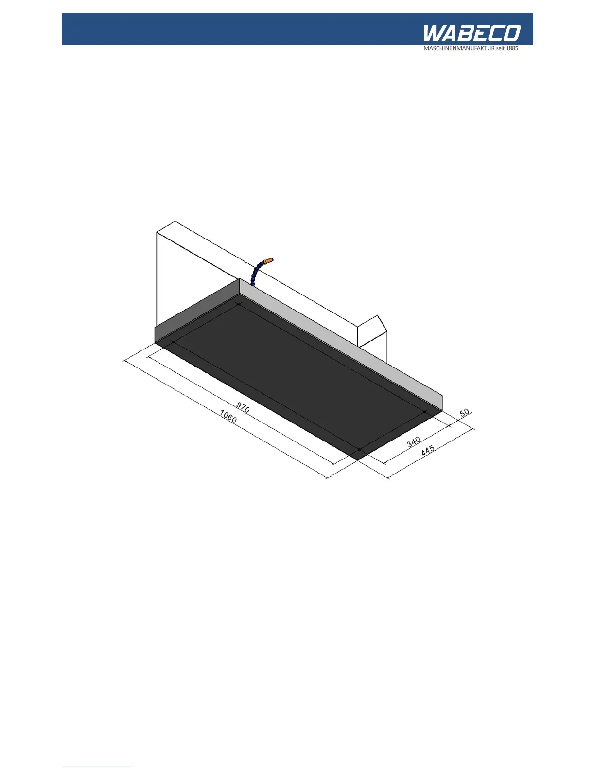
If the coolant system is secured to another suitable surface, the four through holes must be bored into
the surface by the client. For the positions of the four fixtures threaded sockets (thread M8) of the
coolant system, see diagram. The diameter of the through holes in the surface must be at least 9 mm.
22.2 Mounting of the coolant system to the tool cabinet
(optional)
■ The coolant system (2) is positioned, as shown, on the tool cabinet (1)
■ The screws and washers required for assembly are included in the scope of delivery.
To screw the coolant system to the tool cabinet
proceed as follows:
1. Combine each screw with a washer
2. Open the doors of the tool cabinet
3. Push the screws from below, through the bored holes in the tool cabinet, into the fixture threaded
sockets and tighten using an Allen key of size 6.